Snowmobile Ski Doo REV SERIES (2006 year). Manual - part 54


  Index      Snowmobiles / ATV     Snowmobile Ski Doo REV SERIES - service manual 2006 year


Search            


Content   ..  52  53  54  55   ..


Snowmobile Ski Doo REV SERIES (2006 year). Manual - part 54


Section 05 ENGINE MANAGEMENT (POWER TEK)

Subsection 02 (DIAGNOSTIC PROCEDURES)

VCK (VEHICLE COMMUNICATION
KIT)

General

The VCK (Vehicle Communication Kit) (P/N 529
035 981) is the primary tool to diagnose engine
management related problems.

529 035 981

NOTE: The MPEM programmer does not work on
Power TEK models.

Ensure to use the latest version of B.U.D.S. avail-
able on BOSSWeb.

B.U.D.S. (Bombardier Utility and Diagnostic Soft-
ware) is designed to allow electrical component
inspection, diagnostic options and reset such as
the closed throttle.

For more information pertaining to the use of the
software B.U.D.S., use its help which contains de-
tailed information on its functions.

WARNING

If the computer you are using is connected to
the power outlet, there is a potential risk of
electrocution when working in contact with
water. Be careful not to touch water while
working with the VCK.

VCK Supply

The VCK (MPI box) can use the vehicle power for
its supply. Four AA batteries or an AC/DC power
supply can also be used. Make sure to respect
MPI specification if a power supply is used.

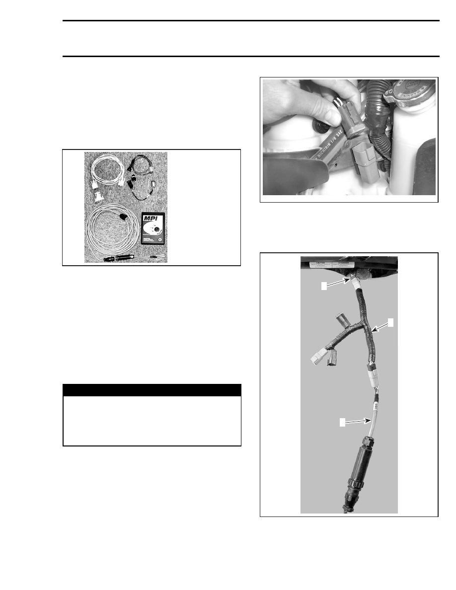
Connecting VCK to Vehicle

Remove the 6 pin connector from the protective
cap on the right side of the vehicle.

A00I0YA

Connect supply harness (P/N 529 035 869), to ve-
hicle 6-pin connector.

Connect the 6 pin diagnostic cable from VCK to
supply harness.

A33E0YA

2

3

1

1. Supply harness
2. Vehicle 6-pin connector
3. VCK cable

mmr2005-106

209

Section 05 ENGINE MANAGEMENT (POWER TEK)
Subsection 02 (DIAGNOSTIC PROCEDURES)

CAUTION: Connecting VCK directly to vehicle
connector (without supply harness) will dam-
age the ECM. Always use the proper supply
harness

A33E0ZA

Connect supply harness to a 12V battery, using
12V battery supply cable (P/N 529 035 997); or to a
9V battery, using 9V battery supply cable (P/N 529
035 675).

529 035 997

12V BATTERY SUPPLY CABLE

A02A0TA

9V BATTERY SUPPLY CABLE

NOTE: The 9V battery allows programming keys,
setting ignition timing, reset closed throttle, etc.
The 12V battery allows to activate solenoids, spark
plugs, etc., from B.U.D.S. Activation tab. In this
case, all sensors and actuators will be continuous-
ly supplied from the battery. The ECM will switch
the circuit to the ground when activated through
B.U.D.S. If engine starting is required, disconnect
clips from battery.

CAUTION: Always use the proper supply har-
ness and cables. Ensure to respect polarity
when connecting cable clips to battery. Match
RED cables together.

NOTE

On all models, it is suggested to disconnect
headlights fuse to reduce battery discharge rate.

On manual start models, it is necessary to use an
external 12V battery and to connect the supply cable
clips on it to supply sensors/actuators.

On electric start models, it is necessary to connect
the supply cable clips to the battery to supply
sensors/actuators.

When using the software B.U.D.S., with the Pow-
er TEK:

– ensure that 115200 speed is properly selected

in “MPI” under “Choose speed”

210

mmr2005-106

Section 05 ENGINE MANAGEMENT (POWER TEK)

Subsection 02 (DIAGNOSTIC PROCEDURES)

A33C5KA

– ensure that the protocol “KW2000” is properly

selected in “MPI” under “Choose protocol

A33C5LA

– ensure the status bar shows the KW2000 and

the number 1 to the right. To communicate
with the ECM, number 1 must be displayed.

Number 1 indicates that the module is recognized
by the MPI.

F18H0WA

kW2000

CONNECTION SUCCESSFUL

If an “X” is shown, this means that no communi-
cation between the MPI and the ECM is possible.
In this case possible causes are:

– ECM is not powered-up
– wrong protocol is used
– bad connection between MPI and module.

When connection is established, a beep pattern
will confirm the diagnostic mode is active.

NOTE: Leaving vehicle in diagnostic mode for a
long period will discharge battery. Be also aware
that some components will generate heat. Al-
ways disconnect VCK supply harness and supply
cable from vehicle/battery when not working on
vehicle.

NOTE: After disconnecting ECM connector for a
test and then reconnecting it, it will be neces-
sary to READ data from vehicle again to re-enable
B.U.D.S. communication. Otherwise, the follow-
ing message will occur.

A33C57A

mmr2005-106

211

Section 05 ENGINE MANAGEMENT (POWER TEK)

Subsection 03 (COMPONENT INSPECTION, REPLACEMENT AND ADJUSTMENT)

COMPONENT INSPECTION,
REPLACEMENT AND ADJUSTMENT

SERVICE TOOLS

Description

Part Number

Page

Fluke 111 .............................................................................. 529 035 868 ......................................... 213
small hose pinchers ............................................................. 295 000 076 ................................. 218, 225

GENERAL

Engine problems are not necessarily related to the
engine management system.

It is important to ensure that the mechanical in-
tegrity of the engine/drive systems are present:

– good transmission system operation
– good engine compression and properly operat-

ing mechanical components, no leaks etc.

Check the chart in TROUBLESHOOTING section
to have an overview of problems and suggested
solutions.

When replacing a component, always check its
operation after installation.

ELECTRICAL SYSTEM

It is important to check that the electrical system
is functioning properly:

– battery
– fuses
– power relay
– DESS
– ignition (spark)
– ground connections
– wiring connectors.

It is possible that a component seems to operate
in static condition but in fact, it is defective. In
this case, the best way to solve this problem is
to remove the original part and replace it with one
which is in good condition.

On electric start models, never use a battery
charger to substitute temporarily the battery, as
it may cause the ECM (engine control module) to
work erratically or not to work at all.

Check related-circuit fuse solidity and condition
with an ohmmeter. Visual inspection could lead
to false results.

To perform verifications, a good quality multimeter
such as Fluke 111 (P/N 529 035 868)should be
used.

529 035 868

Pay particular attention to ensure that pins are
not out of their connectors or out of shape. The
troubleshooting procedures cover problems not
resulting from one of these causes.

CAUTION: Ensure all terminals are properly
crimped on wires and connector housings are
properly fastened.

CAUTION: Check if wiring harness shows any
signs of scoring prior to replace the ECM.

mmr2005-107

213


Content   ..  52  53  54  55   ..