Snowmobile Arctic Cat 2-Stroke (2007 year). Manual - part 158
9-145
9
Servicing ACT Shock
REMOVING/CLEANING
1. Remove the shock from the snowmobile.
2. Wash the shock body in parts-cleaning solvent;
then dry with compressed air to remove sand and
dirt.
DISASSEMBLING
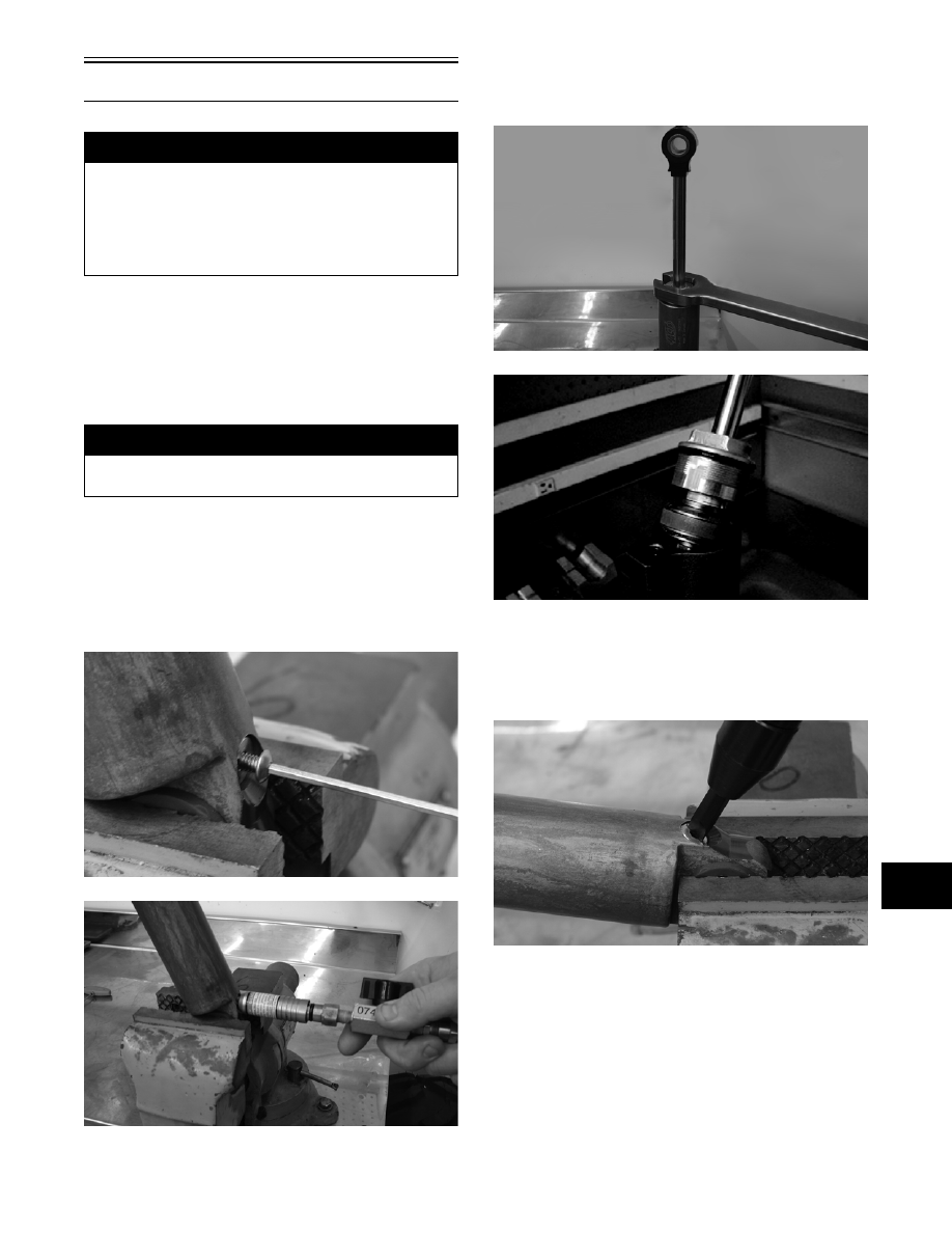
1. Remove the screw from the pressure valve assem-
bly on the bottom of the shock. Discharge all the
pressure from the shock using the Inflation Needle
(p/n 0744-020). Open the valve in filler handle
until all pressure is released.
FS250
FS251
2. Using a 1-in. wrench, loosen the bearing assembly
and remove the shock rod and valve assembly
from the shock body.
FS252
FS055
3. Pour the oil from the shock body into a suitable
container.
4. Remove the pressure valve assembly. Account for
the O-ring.
FS253
5. Using IFP Installation/Location Tool (p/n 0644-
348), remove the floating piston.
! WARNING
Before any service is performed on the gas shock
absorber, first discharge all pressure from the shock
remote reservoir. Remove the valve screw from the
pressure valve and insert the Inflation Needle (p/n
0744-020). Open valve until all pressure is released.
Failure to do this may cause personal injury.
! WARNING
When using compressed air to dry components,
always wear safety glasses.