Snowmobile Arctic Cat 2-Stroke (2007 year). Manual - part 126
9-17
9
Rear Upper Idler
Wheels/Rear Springs
NOTE: The skid frame must be removed for this
procedure (see Removing Skid Frame in this sub-
section).
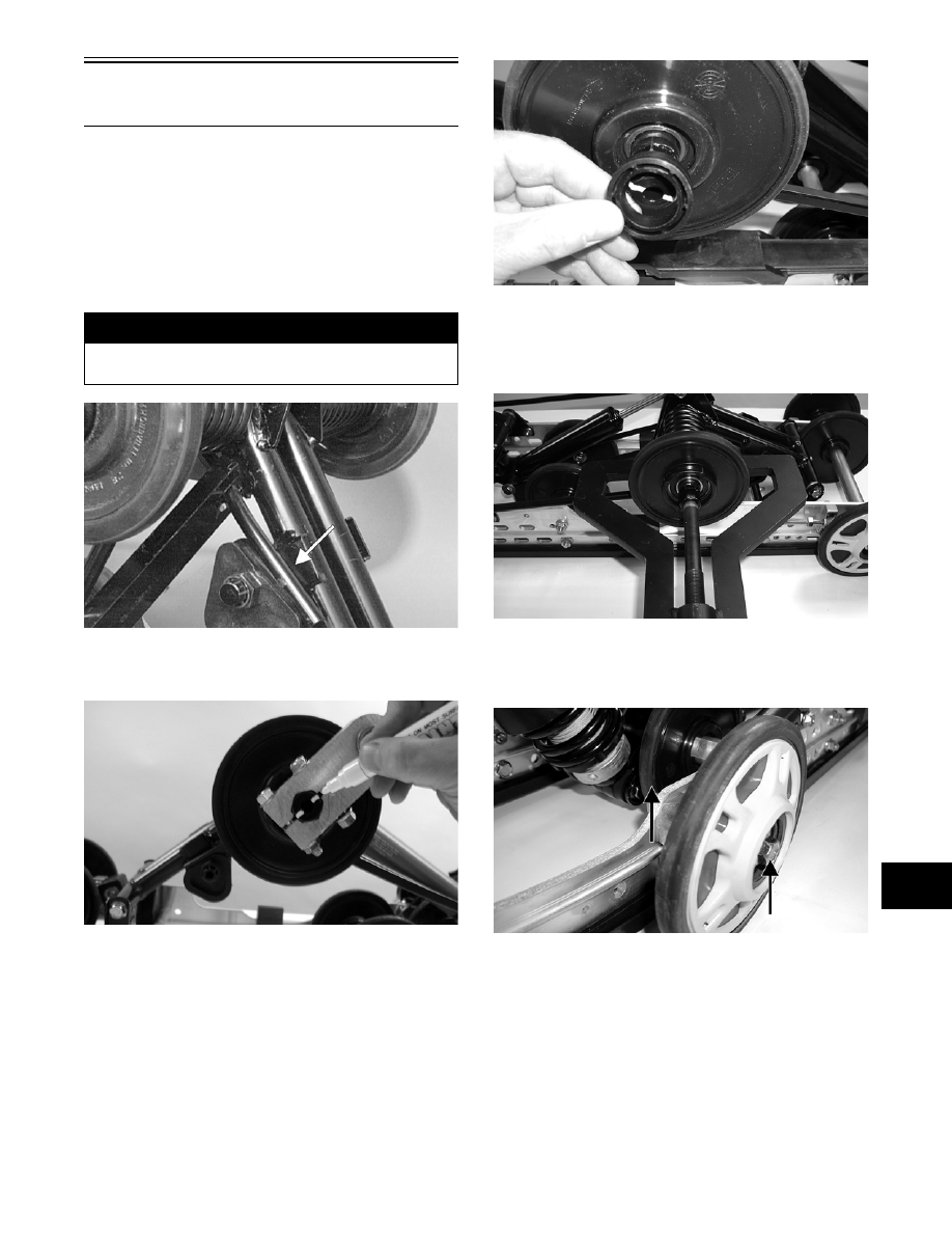
REMOVING
1. Using the Rear Suspension Spring Tool (p/n 0144-
311), remove the spring from the adjusting cam.
AG624DA
2. Mark the offset pivot idler and the idler arm for
assembly purposes.
MS142
3. Remove the cap screws securing the offset pivot
idler arm assembly to the idler arm; then remove
the offset pivot arm idler assembly. Account for a
flanged axle, flared bushing, idler spacer collar,
and lock nuts.
MS064
4. Remove the idler wheel.
NOTE: Use Idler Wheel Puller Kit (p/n 0644-122)
to remove the wheel.
MS011
5. Remove the cap screw and flat washer securing
the front outer idler wheel to the mounting block
and remove the idler wheel.
MS002B
6. Remove the cap screw, flat washer, and lock nut
securing the spring slide to the slide rail. Account
for the spring slide and all mounting hardware.
! WARNING
Care must be taken when removing the spring or
damage or injury could result.