Snowmobile Arctic Cat 2-Stroke (2007 year). Manual - part 70
5-10
3. With all switches in the RUN position, the meter
must read resistance (closed). If the meter reads no
resistance (open), proceed to testing Emergency
Stop/Throttle Switch, Carburetor Safety Switches,
and Ignition Key Switch.
EMERGENCY STOP/
THROTTLE SWITCH
1. If the meter read no resistance (open) in the previ-
ous test, locate the wiring harness coming from the
emergency stop/throttle switch assembly.
2. Disconnect the three-wire connector. Using an
ohmmeter, connect one meter lead to the black
wire and the other meter lead to the black/red wire
in the connector.
3. With the emergency stop knob, located on top of
the throttle control, in the ON (pulled up) position
and the throttle lever compressed, the meter must
read resistance (closed).
4. If the meter reads no resistance (open) and the
lever/control housing free-play is correct, replace
the throttle switch.
5. If the meter reads resistance (closed) but the
engine will not start, with the ohmmeter leads still
connected, alternately release and compress the
throttle lever; then move the emergency stop knob
down and up.
6. The meter must read no resistance (open) when the
throttle lever is released and the emergency stop
knob is in either the UP or the DOWN position.
7. If the meter reads resistance (closed), replace the
throttle switch.
8. Connect one meter lead to the black/red wire and
the other meter lead to the black/white wire.
9. With the throttle lever released (idle position) and
the emergency stop knob in the DOWN position,
the meter must read no resistance (open).
10. If above tests were good, proceed to testing Carbu-
retor Safety Switches and Ignition Key Switch.
CARBURETOR SAFETY SWITCHES
1. If the meter read no resistance (open) in the previ-
ous test, disconnect the carburetor safety switches
one at time and test for a closed circuit.
2. Attach the two ohmmeter leads to the two leads
coming from each carburetor switch. The meter
must read resistance (closed).
3. If the meter reads no resistance (open), the switch
must either be adjusted or replaced (see Synchro-
nizing Carburetor Safety Switches in this sub-sec-
tion). If the meter reads resistance (closed),
proceed to testing Ignition Key Switch.
IGNITION KEY SWITCH
1. If the meter read resistance (closed) in the previ-
ous test, disconnect the ignition key switch con-
nectors and connect the ohmmeter leads to each of
the leads from the switch.
2. With the key switch in the OFF position, the meter
must read resistance (closed). If the meter reads no
resistance (open), replace the switch.
SYNCHRONIZING CARBURETOR
SAFETY SWITCHES
Before synchronizing the carburetor safety switches,
check to make certain the carburetor idle speed screws
are adjusted equally and the piston valves are synchro-
nized. The carburetor safety switches affect ignition
spark at idle only. If ignition spark problems are
observed at partial or full-throttle positions, the prob-
lem is not with the carburetor safety switches.
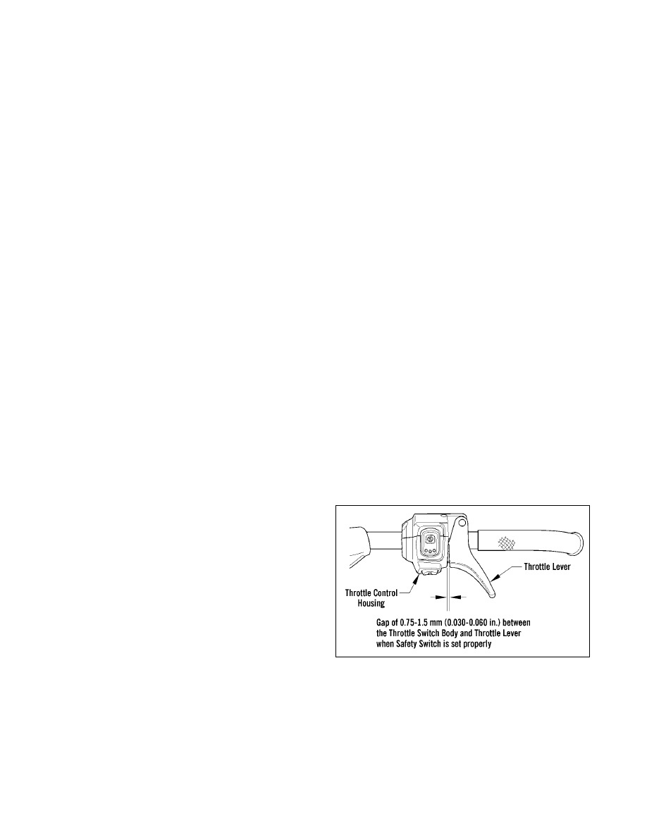
NOTE: There must be 0.75-1.5 mm (0.030-0.060
in.) free-play between the throttle lever and the
control housing.
1. Inspect the cable free-play gap between the throt-
tle lever and the control housing at idle. Adjust the
throttle cable swivel adapter at the top of each car-
buretor for 0.75-1.5 mm (0.030-0.060 in.) cable
free-play gap between the throttle lever “nibs” and
the control housing. While observing if there is
any cable free-play gap, apply slight pressure to
the throttle lever to take up any cable slack that
may be present. However, do not apply enough
pressure to actually raise the carburetor slides dur-
ing this adjustment. After cable free-play is prop-
erly adjusted, tighten the jam nut on each
carburetor securely.
0741-518
2. To determine which switch needs adjusting, dis-
connect both carburetor safety switches from the
main wiring harness connector.
3. Connect a digital ohmmeter to one carburetor
safety switch connector; then compress the throttle
lever while observing the meter reading and mea-
sure the gap between the throttle lever and control
housing at the moment the meter reading changes
from open to closed. Repeat this step for the other
carburetor safety switch.