Snowmobile Arctic Cat 2-Stroke (2007 year). Manual - part 45


  Index      Snowmobiles / ATV     Snowmobile Arctic Cat 2-Stroke - service manual 2007 year


Search            


Content   ..  43  44  45  46   ..


Snowmobile Arctic Cat 2-Stroke (2007 year). Manual - part 45


2-166

742-197A

15. On the 800 cc, tighten cap screw (11) in three steps

to specifications; then turn the engine right-side up

and tighten cap screws (12-15) in three steps to

specifications.

16. On the 1000 cc, tighten cap screws (11-13) in three

steps to specifications; then tighten cap screw (14)

in three steps to specifications.

„NOTE: Secure the connecting rods with rubber
hoses.

17. Install the oil-injection pump retainer with a new

O-ring.

FC082

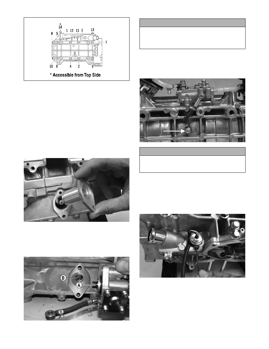
18. Install the O-ring and the oil-injection pump mak-

ing sure the pump shaft slot (A) and pump driven

gear shaft (B) align. Secure with two screws

(coated with blue Loctite #243). Tighten the two

screws to specifications.

CM167A

19. Install the oil-injection hoses and secure with the

clamps; then place the lower union assembly into

position and secure with new gaskets and union

cap screw. Tighten to specifications.

CM153A

20. Secure the intake flanges, reed valve assemblies,

and gaskets with cap screws; then in a crisscross

pattern, tighten to specifications.

21. Install the coolant temperature sensor and tighten

securely; then secure the sensor wire to the sensor

with a cable tie.

CM172

22. Position the ceramic/rubber seal into the back side

of the water pump impeller with the ceramic face

of the seal directed out.

1000 cc

! CAUTION

Be sure the oil-injection pump/water pump drive-
shaft is properly aligned with the slot of the oil-injec-
tion pump. The pump will be damaged if these two
components are not aligned.

! CAUTION

Assure that a new gasket is in place on each side of
the union prior to securing the union cap screw to
the crankcase.

2-167

2

CM168

23. Using both thumbs, press the seal into position

making sure its marked side is positioned towards

the rubber seal cup; then apply a thin coat of

grease to the seal outer surface.

CM169

24. Place the impeller into position and secure with a

cap screw and washer. Be sure the rubber side of

the washer is directed toward the impeller. Apply

blue Loctite #243 to the threads of the cap screw

and tighten to specifications.

25. Apply high-temperature sealant to the crankcase/

water pump cover seam; then install the dowel

pins into the crankcase.

CM171A

CM171B

„NOTE: Sealant is only required on the crankcase
seam.

26. Apply a thin film of low-temp grease to the water

pump cover O-ring; then position the O-ring into

the water pump cover. With the alignment pins in

place, install the cover. Secure with seven screws

using the pattern shown. Tighten to specifications.

0742-257

27. With the bypass valve of the thermostat directed to

the 12 o’clock position, install the thermostat and

housing; then in a crisscross pattern, tighten the

cap screws to specifications.

CM157A

! CAUTION

The rubber side of the washer, which secures the
impeller, must be positioned toward the impeller. If
installed incorrectly, a coolant leak will result.

2-168

CM155A

28. Place the cylinder base gasket into position on the

crankcase.

29. Install the piston rings on each piston so the letter

on the top (inclined surface) of each ring faces the

dome of the piston.

726-306A

30. Apply oil to the connecting-rod small end bear-

ings; then install the small-end bearings. Install a

washer on each side of the connecting rod.

„NOTE: The shoulder side of the washer must
seat to the needle bearing.

CM172A

31. Place each piston over the connecting rod so the

indicator dot on each piston will point toward the

intake/exhaust ports; then secure with an oiled pis-

ton pin.

„NOTE: The indicator dot is found on the piston
dome.

CM173

32. Install the new circlips so the open end is directed

either up or down.

CM174

33. Rotate each piston ring until the ring ends are

properly positioned on either side of the ring

keeper; then apply oil to the piston assemblies and

cylinder bores. Remove the rubber hoses from the

connecting rods.

34. In turn on each cylinder, place a piston holder (or

suitable substitute) beneath the piston skirt and

square the piston in respect to the crankcase; then

using a ring compressor or the fingers, compress

the rings and slide the cylinder over the piston.

Remove the piston holder and seat the cylinder

firmly onto the crankcase.

„NOTE: The cylinders should slide on easily. DO
NOT force the pistons into the cylinders.

! CAUTION

Incorrect installation of the piston rings will result in
engine damage.

! CAUTION

Make sure the circlips are firmly seated and the open
end is directed either up or down before continuing
with assembly.

2-169

2

CM148

35. Secure each cylinder by installing the four nuts

and four new cap screws. DO NOT TIGHTEN AT

THIS TIME.

„NOTE: Always use new cap screws when install-
ing the cylinders.

36. Secure the cylinders (from step 35) by tightening

the cylinder base nuts and cap screws to specifica-

tions in three steps using the appropriate pattern

shown.

0738-206

0738-220

37. Install the two cylinder O-rings on the top of each

cylinder making sure they are correctly positioned

in the grooves.

FC077

38. Place new O-rings onto each of the head cap

screws. Place four of these cap screws (from oppo-

site end of each other) into the cylinder head.

Thread the spark plugs in part way; then while

holding the head above the cylinder, carefully start

and finger-tighten all four cap screws while

observing the cylinder O-rings to make sure they

remain in position. Slowly place the head into

position on top of the O-rings.

CM175

„NOTE: On the 800 cc prior to starting the remain-
ing cap screws, the spark plugs must be removed.

39. Start and finger-tighten the remaining cap screws

being very careful not to move the cylinder head;

then tighten the cap screws in two steps to specifi-

cations using the appropriate pattern shown.

0742-200

800 cc

1000 cc

800 cc


Content   ..  43  44  45  46   ..