Snowmobile Arctic Cat 2-Stroke (2007 year). Manual - part 42


  Index      Snowmobiles / ATV     Snowmobile Arctic Cat 2-Stroke - service manual 2007 year


Search            


Content   ..  40  41  42  43   ..


Snowmobile Arctic Cat 2-Stroke (2007 year). Manual - part 42


2-154

3. Using Flywheel Puller (p/n 0744-040) or suitable

substitute, remove the flywheel from the crank-

shaft by tightening the puller bolt, striking the

head of the puller bolt with a hammer, and tighten-

ing again. Repeat this procedure until the flywheel

is free. Account for the key.

CM140

„NOTE: To ensure the cleanliness of the flywheel
magnets, place the flywheel (with the magnets fac-
ing upward) on a clean bench.

„NOTE: On the 1000 cc, remove the Allen-head
cap screws securing the magneto case to the
crankcase. Account for four alignment pins.

CM144A

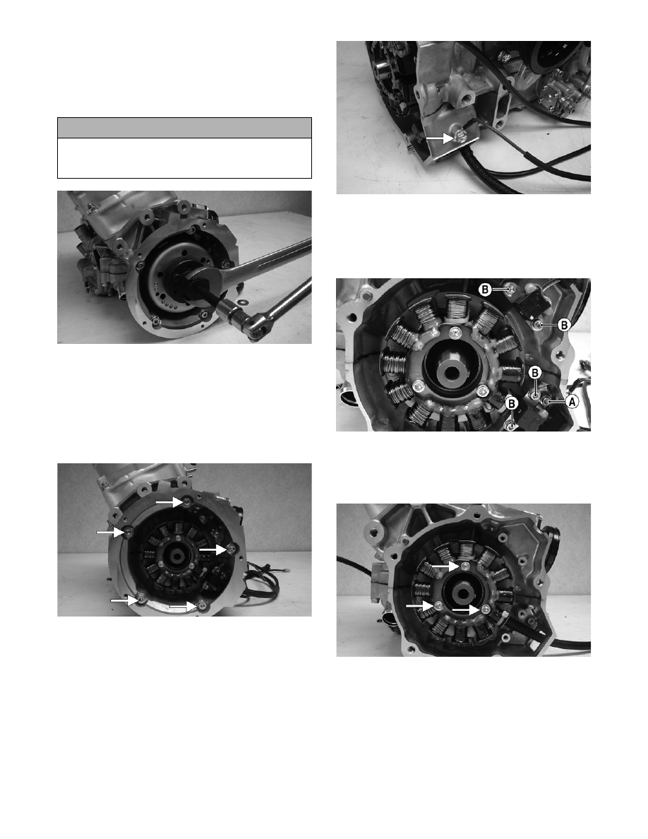
4. Remove the cap screw securing the ground wire to

the crankcase.

CM142A

5. Remove the Allen-head cap screw (A) securing

the stator lead wire plate to the crankcase; then

remove the Allen-head cap screws (B) securing

the timing sensors, remove the sensors, and

account for the harness grommets.

CM141C

6. Remove the Allen-head cap screws securing the

stator to the stator plate. Route the stator lead wire

out of the crankcase; then remove the stator

assembly.

CM143A

7. Remove the cap screws securing the stator plate to

the engine; then remove the plate.

! CAUTION

To prevent damage to the crankshaft, do not thread
puller bolts more than 12.7 mm (1/2 in.) into the fly-
wheel. Damage to the coils may result.

2-155

2

CM145D

„NOTE: For assembling purposes, note that the
indentation (A) of the stator plate is aligned with
the harness opening (B) in the crankcase.

CM145C

„NOTE: The stator plate screws had Loctite
applied to the threads during assembly. Using an
impact driver, apply a sharp blow to the head of
each screw to break the Loctite loose before
removal.

8. Remove the cap screws securing the APV assem-

blies to the cylinders; then remove the APV

assemblies and set them aside.

„NOTE: For assembling purposes, note that the
APV exhaust valves and gaskets are directional.

CM146A

CM147

9. Remove the spark plugs.

„NOTE: On the 800 cc at this point, remove the
knock sensor and lock plate from the cylinder
head by bending the lock plate tabs down and
unthreading the sensor.

10. Remove the cap screws with O-rings securing the

cylinder head; then separate from the cylinders.

Account for the O-rings.

„NOTE: When removing the cylinders, place the
engine on its intake flanges on a drain tray to allow
residual coolant to drain from the cylinder/crank-
case water jacket.

11. Remove the four nuts and four cap screws secur-

ing the cylinders to the crankcase; then using a soft

hammer, gently tap the cylinders and remove from

the crankcase by lifting them straight up off their

studs. Account for gasket(s) and alignment pins.

CM148

12. Remove the PTO-side piston-pin circlip from the

PTO-side piston; then remove the MAG-side pis-

ton-pin circlip from the MAG-side piston.

! CAUTION

When removing a cylinder, be sure to support the
piston to prevent damage to the crankcase and pis-
ton.

2-156

CM149

13. Using Piston Pin Puller (p/n 0644-328), remove

the piston pins from both pistons.

„NOTE: For proper assembly, keep all MAG-side
components and all PTO-side components sepa-
rated. Assemble them on their proper sides.

CM150

14. Lift the pistons clear of the connecting rods and

remove the small-end connecting-rod bearings

(account for two washers); then remove the piston

rings. Keep each piston with its rings; keep each

piston pin and bearing together as a set.

CM151

„NOTE: Place a suitable length of rubber hose
around the connecting rods. This will prevent the
connecting rods from damaging the crankcase.

15. Remove the intake flanges and reed valve assem-

blies.

CM152

16. Remove the lower union cap screw securing the

lower check valve assembly to the crankcase; then

remove the two screws securing the oil-injection

pump to the crankcase. Remove the pump,

retainer, and O-ring and account for the two gas-

kets from the lower union.

CM153A

CM154A

17. Remove the four cap screws securing the thermo-

stat cap; then remove the cap, gasket, and thermo-

stat.

! CAUTION

DO NOT use any type of punch to drive the piston
pin free of the piston; damage may result. Use a pis-
ton-pin puller only.

2-157

2

CM155A

„NOTE: For assembling purposes, note that the
positioning of the bypass/check valve is directed
up.

CM157A

18. Remove the seven cap screws securing the water

pump cover to the crankcase and remove the

cover. Account for the O-ring gasket and the align-

ment pins.

CM156A

19. Remove the cap screw securing the water pump

impeller; then slide the impeller free of the shaft.

20. Prior to turning the engine upside down on the 800

cc, remove the two crankcase Allen-head cap

screws from the water pump side of the engine;

then remove the two cap screws from the magneto

housing. On the 1000 cc, remove the one crank-

case Allen-head cap screw located above the ther-

mostat housing.

21. Turn the engine upside down on support blocks,

cut the cable tie, and remove the water tempera-

ture sensor switch.

22. With its bottom side up on two support blocks,

remove the cap screws securing the crankcase

halves.

„NOTE: The end bearings are not pressed onto
the crankshaft.

23. Separate the crankcase halves by installing two

crankcase cap screws in opposite corners leaving

the heads approximately 6 mm (1/4 in.) out. Using

a plastic hammer and lifting on the ends of the

crankshaft, tap on each cap screw head until the

case halves separate. Remove the cap screws.

CM158

24. Lift the bottom half of the crankcase off the top

half.

25. Lift the crankshaft free from the top half of the

crankcase and slide the crankshaft oil seals off the

crankshaft. Account for the C-ring (A). Remove

the bearing retaining pins (B) and account for the

crankcase dowel pins (C).

! CAUTION

DO NOT drive any tool between halves to separate
the crankcase. Damage to the sealing surfaces will
result.

! CAUTION

Care must be taken to not allow the connecting rods
to drop onto the sealing surface of the bottom case
half.


Content   ..  40  41  42  43   ..