Snowmobile Arctic Cat 2-Stroke (2007 year). Manual - part 36


  Index      Snowmobiles / ATV     Snowmobile Arctic Cat 2-Stroke - service manual 2007 year


Search            


Content   ..  34  35  36  37   ..


Snowmobile Arctic Cat 2-Stroke (2007 year). Manual - part 36


2-130

4. Place the cylinder heads on a Surface Plate (p/n

0644-016) covered with #400 grit wet-or-dry

sandpaper. Using light pressure, move each cylin-

der head in a figure eight motion. Inspect the seal-

ing surface for any indication of high spots. A high

spot can be noted by a bright metallic finish. Cor-

rect any high spots before assembly by continuing

to move the cylinder head in a figure eight motion

until a uniform bright metallic finish is attained.

CM018

CYLINDERS

1. Using a non-metallic carbon removal tool, remove

carbon buildup from the exhaust ports.

2. Wash the cylinders in parts-cleaning solvent.

3. Inspect the cylinders for pitting, scoring, scuffing,

and corrosion. If marks are found, repair the sur-

face with an appropriate ball hone and honing oil

(see chart).

„NOTE: To produce the proper 60° crosshatch pat-
tern, use a low RPM drill (600 RPM) at the rate of 30
strokes per minute. If honing oil is not available,
use a lightweight, petroleum-based oil. Thoroughly
clean the cylinders after honing using detergent
soap and hot water and dry with compressed air;
then immediately apply oil to the cylinder bores. If
a bore is severely damaged or gouged, the cylin-
der will have to be replaced.

4. Place the head surface of each cylinder on the sur-

face plate covered with #400 grit wet-or-dry sand-

paper. Using light pressure, move each cylinder in

a figure eight motion. Inspect the surface for any

indication of high spots. A high spot can be noted

by a bright metallic finish. Correct any high spots

before assembly by continuing to move the cylin-

der in a figure eight motion until a uniform bright

metallic finish is attained.

PISTON ASSEMBLY

1. Using a non-metallic carbon removal tool, remove

the carbon buildup from the dome of each piston.

2. Take an old piston ring and snap it into two pieces;

then grind the end of the old ring to a 45° angle

and to a sharp edge. Using the sharpened ring as a

tool, clean carbon from the ring-grooves. Be sure

to position the ring with its tapered side up.

3. Inspect each piston for cracks in the piston pin and

skirt areas.

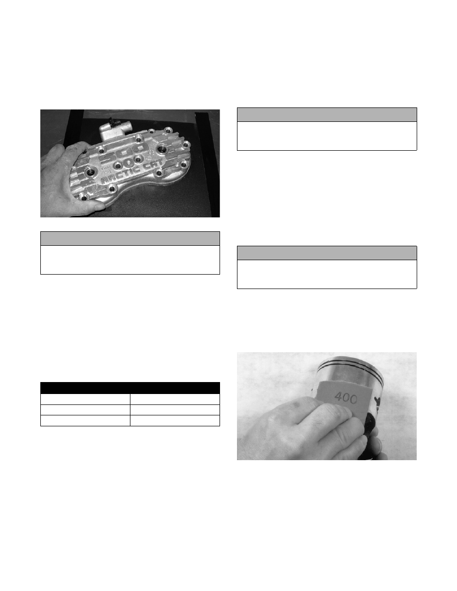
4. Inspect each piston for seizure marks or scuffing.

Repair with #400 grit wet-or-dry sandpaper and

water or honing oil.

AN135

„NOTE: If scuffing or seizure marks are too deep
to correct with the sandpaper, it will be necessary
to replace the piston.

5. Inspect the perimeter of each piston for signs of

excessive “blowby.” Excessive “blowby” indicates

worn piston rings or an out-of-round cylinder.

! CAUTION

Water or parts-cleaning solvent must be used in
conjunction with the wet-or-dry sandpaper or dam-
age to the sealing surface may result.

BALL HONES

Engine Size

p/n

500 cc

0644-291

600 cc

0644-292

! CAUTION

Water or parts-cleaning solvent must be used in
conjunction with the wet-or-dry sandpaper or dam-
age to the sealing surface may result.

! CAUTION

Improper cleaning of the ring-grooves by the use of
the wrong type of ring-groove cleaner will result in
severe damage to the piston.

2-131

2

CRANKCASE

1. Wash the crankcase halves in parts-cleaning sol-

vent.

„NOTE: Before washing the crankcase halves,
make sure the four bearing dowel pins have been
removed and accounted for.

2. Inspect the crankcase halves for scoring, pitting,

scuffing, or any imperfections in the casting.

3. Inspect all threaded areas for damaged or stripped

threads.

4. Inspect the bearing areas for cracks or excessive

bearing movement. If evidence of excessive bear-

ing movement is noted, repair by peening the bear-

ing area in a pinking (sawtooth) pattern.

5. Inspect the bearing dowel pins for wear.

6. Inspect the sealing surfaces of the crankcase

halves for trueness by placing each crankcase half

on the surface plate covered with #400 grit wet-or-

dry sandpaper. Using light pressure, move each

half in a figure eight motion. Inspect the sealing

surfaces for any indication of high spots. A high

spot can be noted by a bright metallic finish. Cor-

rect any high spots by continuing to move the half

in a figure eight motion until a uniform bright

metallic finish is attained.

„NOTE: Care must be taken not to remove an
excessive amount of aluminum, or the crankcase
will have to be replaced. If excessive aluminum is
removed, too much pre-load will be exerted on the
crankshaft bearings when assembled.

CM160

CRANKSHAFT

„NOTE: If any servicing of the connecting rods,
center bearings, or oil-injection pump drive gear is
necessary, Arctic Cat recommends that the crank-
shaft be taken to a qualified machine shop for that
service.

1. Wash the crankshaft with bearings in parts-clean-

ing solvent.

2. Inspect the bearings for wear, scoring, scuffing,

damage, or discoloration. Rotate the bearings.

Bearings must rotate freely and must not bind or

feel rough. If any abnormal condition is noted,

replace the bearing.

FC039

3. Inspect the connecting-rod bearings by rotating

them. The bearings must rotate freely and must not

bind or feel rough. If a connecting-rod bearing

must be replaced, the connecting rod and crank pin

must also be replaced.

FC040

4. Inspect the oil-injection pump drive gear for any

signs of worn or chipped teeth. If either condition

exists, replace the gear.

„NOTE: Lubricate bearings thoroughly prior to
assembly.

! CAUTION

Water or parts-cleaning solvent must be used in
conjunction with the wet-or-dry sandpaper or dam-
age to the sealing surface may result.

2-132

REMOVING/INSTALLING OUTER 
CRANKSHAFT BEARINGS

„NOTE: The end bearings are not pressed onto
the crankshaft. The bearings can be removed sim-
ply by sliding them off the crankshaft.

CM161

„NOTE: Install the bearings by sliding each bear-
ing onto the crankshaft making sure the dowel-pin
hole in the outer race is properly positioned and
will align with its hole and pin in the crankcase.

CM161

REED VALVE ASSEMBLY

1. Inspect the reed valves, stoppers, and valve blocks

for cracks or any deterioration.

CM162

2. Wash the reed valves, stopper, and cage assembly

in parts-cleaning solvent and blow dry.

3. Inspect the reed stopper height. Using a caliper,

measure the distance from the seat to the bottom

outer tip edge of the stopper. Measurement must

not exceed specifications. If measurement is not

within specifications, either bend or replace the

reed stopper.

AJ156

4. Inspect the reed-to-seat clearance. Using a feeler

gauge, measure the clearance. Clearance must be

less than 0.20 mm (0.008 in.). If clearance is not

within specifications, replace the reed valve.

5. To assemble, place the reed valves on the cage

with its clipped corner positioned to the lower

right hand corner of the cage. Place the reed stop-

per assembly into position and secure with the

screws coated with red Loctite #271.

CM164A

Measuring Critical 

Components

„NOTE: Critical engine specifications charts can
be found at the beginning of this section.

CYLINDER HEAD VOLUME 
(Squish-Gap Method)

To check the squish gap, a micrometer and a heavy

piece of solder will be needed.

1. Remove the spark plugs from the engine.

2-133

2

2. Insert the solder piece down through the spark

plug hole and push it up against the inner cylinder

bore towards the MAG-side of the engine.

3. Pull the recoil rope and crank the engine over sev-

eral times while the solder is being held firmly in

place.

4. Remove the solder from the cylinder. Using the

micrometer, measure the very end of the squeezed

solder piece. Record the reading.

„NOTE: If the solder hasn’t been squeezed by the
piston, a larger piece of solder must be used.
Repeat procedure.

5. Using the opposite end of the solder piece, insert it

down through the spark plug hole towards the

PTO-side of the engine. Push on the solder until it

contacts the inner cylinder bore.

6. Pull the recoil rope and crank the engine over sev-

eral times. Remove the solder from the cylinder

and measure the squeezed end with a micrometer.

Record reading and refer to the chart.

„NOTE: Measure from PTO to MAG-side of the pis-
ton to accurately measure the squish gap. Never
measure across piston, exhaust to carburetor
side, as the piston will rock and the reading won’t
be accurate.

Readings may vary from side to side. Make sure the

smaller reading is within the specifications listed.

CYLINDER TRUENESS

1. Measure each cylinder in the three locations from

front to back and side to side for a total of six read-

ings.

FC044

2. The trueness (out-of-roundness) is the difference

between the highest and lowest reading. Maxi-

mum trueness (out-of-roundness) must not exceed

specifications.

0725-586

PISTON SKIRT/CYLINDER 
CLEARANCE

1. Measure each cylinder front to back about 2.5 cm

(1 in.) from the bottom of each cylinder.

2. Measure the corresponding piston skirt diameter at

a point 1 cm (0.394 in.) above the piston skirt at a

right angle to the piston-pin bore. Subtract this

measurement from the measurement in step 1. The

difference (clearance) must be within specifica-

tions.

AC091

PISTON-RING END GAP

1. Place each piston ring in the wear portion above

the exhaust port of its respective cylinder. Use the

piston to position each ring squarely in each cylin-

der.

2. Using a feeler gauge, measure each piston-ring

end gap. Acceptable ring end gap must be within

specifications.


Content   ..  34  35  36  37   ..