Snowmobile Arctic Cat 2-Stroke (2007 year). Manual - part 14


  Index      Snowmobiles / ATV     Snowmobile Arctic Cat 2-Stroke - service manual 2007 year


Search            


Content   ..  12  13  14  15   ..


Snowmobile Arctic Cat 2-Stroke (2007 year). Manual - part 14


2-42

MD0090

MD0092A

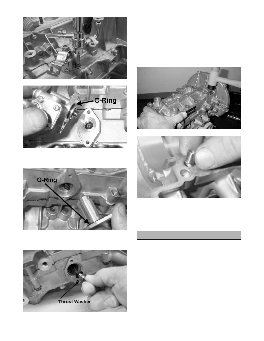
20. Remove the oil-injection pump driveshaft retainer.

Account for an O-ring.

MD0100A

21. Remove the oil-injection pump driveshaft.

Account for a thrust washer.

MD0101

22. Place the crankcase (with its bottom side up) on

two blocks of wood. Remove the 12 cap screws

securing the crankcase halves. Note the position of

the different-sized cap screws.

23. Separate the crankcase halves by installing two of

the cap screws in opposite corners leaving the heads

approximately 6 mm (1/4 in.) out. Using a plastic

mallet, tap on each cap screw until the crankcase

halves separate. Account for four dowel pins.

MD0283

MD0204

24. Remove the two cap screws; then remove the

crankshaft assembly from the upper crankcase half

making sure to hold both ends of the crankshaft to

keep the bearings and seals from falling off.

Account for bearings and a C-ring.

! CAUTION

To prevent damage to the crankshaft, crankshaft
bearings, or seals, be sure to always lift the crank-
shaft from both ends.

2-43

2

MD0246

Cleaning and Inspecting 

Engine

„NOTE: Whenever a part is worn excessively,
cracked, or damaged in any way, replacement is
necessary.

CYLINDER HEAD

1. Using a non-metallic carbon removal tool, remove

any carbon buildup from the combustion chambers

being careful not to nick, scrape, or damage the

combustion chambers or the sealing surfaces.

2. Inspect the spark-plug holes for any damaged

threads. Repair damaged threads using a heli-coil

insert.

3. Inspect the cylinder head for flatness using a

straightedge and a feeler gauge. Acceptable

warpage must not exceed 0.05 mm (0.002 in.).

„NOTE: If the warpage exceeds specification,
resurface the cylinder head using procedures
identified in step 4.

MD2491

4. Place the cylinder head on a Surface Plate (p/n

0644-016) covered with #400 grit wet-or-dry

sandpaper. Using light pressure, move each cylin-

der head in a figure eight motion. Inspect the seal-

ing surface for any indication of high spots. A high

spot can be noted by a bright metallic finish. Cor-

rect any high spots before assembly by continuing

to move the cylinder head in a figure eight motion

until a uniform bright metallic finish is attained.

MD2492

CYLINDERS

1. Using a non-metallic carbon removal tool, remove

carbon buildup from the exhaust ports.

2. Wash the cylinders in parts-cleaning solvent.

3. Inspect the cylinders for pitting, scoring, scuffing,

and corrosion. If marks are found, repair the sur-

face with an appropriate ball hone and honing oil

(see chart).

„NOTE: To produce the proper 60° crosshatch pat-
tern, use a low RPM drill (600 RPM) at the rate of 30
strokes per minute. If honing oil is not available,
use a lightweight, petroleum-based oil. Thoroughly
clean the cylinders after honing using detergent
soap and hot water and dry with compressed air;
then immediately apply oil to the cylinder bores. If
a bore is severely damaged or gouged, the cylin-
der will have to be replaced.

! CAUTION

Water or parts-cleaning solvent must be used in
conjunction with the wet-or-dry sandpaper or dam-
age to the sealing surface may result.

BALL HONE

Engine Size

p/n

570 cc

0644-292

2-44

4. Place the head surface of each cylinder on the sur-

face plate covered with #400 grit wet-or-dry sand-

paper. Using light pressure, move each cylinder in

a figure eight motion. Inspect the surface for any

indication of high spots. A high spot can be noted

by a bright metallic finish. Correct any high spots

before assembly by continuing to move the cylin-

der in a figure eight motion until a uniform bright

metallic finish is attained.

PISTON ASSEMBLY

1. Using a non-metallic carbon removal tool, remove

the carbon buildup from the dome of each piston.

2. Take an old piston ring and snap it into two pieces;

then grind the end of the old ring to a 45° angle

and to a sharp edge. Using the sharpened ring as a

tool, clean carbon from the ring-grooves. Be sure

to position the ring with its tapered side up.

3. Inspect each piston for cracks in the piston pin and

skirt areas.

4. Inspect each piston for seizure marks or scuffing.

Repair with #400 grit wet-or-dry sandpaper and

water or honing oil.

AN135

„NOTE: If scuffing or seizure marks are too deep
to correct with the sandpaper, it will be necessary
to replace the piston.

5. Inspect the perimeter of each piston for signs of

excessive “blowby.” Excessive “blowby” indicates

worn piston rings or an out-of-round cylinder.

CRANKCASE

1. Wash the crankcase halves in parts-cleaning sol-

vent.

„NOTE: Before washing the crankcase halves,
make sure the four bearing dowel pins have been
removed and accounted for.

2. Inspect the crankcase halves for scoring, pitting,

scuffing, or any imperfections in the casting.

3. Inspect all threaded areas for damaged or stripped

threads.

4. Inspect the bearing areas for cracks or excessive

bearing movement. If evidence of excessive bear-

ing movement is noted, repair by peening the bear-

ing area in a pinking (sawtooth) pattern.

5. Inspect the bearing dowel pins for wear.

6. Inspect the sealing surfaces of the crankcase

halves for trueness by placing each crankcase half

on the surface plate covered with #400 grit wet-or-

dry sandpaper. Using light pressure, move each

half in a figure eight motion. Inspect the sealing

surfaces for any indication of high spots. A high

spot can be noted by a bright metallic finish. Cor-

rect any high spots by continuing to move the half

in a figure eight motion until a uniform bright

metallic finish is attained.

„NOTE: Care must be taken not to remove an
excessive amount of aluminum, or the crankcase
will have to be replaced. If excessive aluminum is
removed, too much pre-load will be exerted on the
crankshaft bearings when assembled.

MD0200A

ADAPTER PLATES

1. Inspect for cracks, scoring, pitting, imperfections,

or warping.

! CAUTION

Water or parts-cleaning solvent must be used in
conjunction with the wet-or-dry sandpaper or dam-
age to the sealing surface may result.

! CAUTION

Improper cleaning of the ring-grooves by the use of
the wrong type of ring-groove cleaner will result in
severe damage to the piston.

! CAUTION

Water or parts-cleaning solvent must be used in
conjunction with the wet-or-dry sandpaper or dam-
age to the sealing surface may result.

2-45

2

2. Inspect the sealing surfaces for trueness by placing

each on the surface plate covered with #400 grit

wet-or-dry sandpaper. Using light pressure, move

both sides in a figure eight motion. Inspect the

sealing surface for any indication of high spots or

warping. Correct high spots by continuing to move

each side in a figure eight motion. Warped compo-

nents must be replaced.

„NOTE: In order to inspect adapter plate trueness,
it will be necessary to remove the studs.

A932

CRANKSHAFT

„NOTE: If any servicing of the connecting rods,
center bearings, or oil-injection pump drive gear is
necessary, Arctic Cat recommends that the crank-
shaft be taken to a qualified machine shop for that
service.

1. Wash the crankshaft with bearings in parts-clean-

ing solvent.

2. Inspect the bearings for wear, scoring, scuffing,

damage, or discoloration. Rotate the bearings.

Bearings must rotate freely and must not bind or

feel rough. If any abnormal condition is noted,

replace the bearing.

FC039

3. Inspect the connecting-rod bearings by rotating

them. The bearings must rotate freely and must not

bind or feel rough. If a connecting-rod bearing

must be replaced, the connecting rod and crank pin

must also be replaced.

FC040

4. Inspect the oil-injection pump drive gear for any

signs of worn or chipped teeth. If either condition

exists, replace the gear.

„NOTE: Lubricate bearings thoroughly prior to
assembly.

REMOVING OUTER 
CRANKSHAFT BEARINGS

„NOTE: Steps 1-2 are for removing the MAG-side
bearing.

1. Place the crankshaft in a suitable support; then

install Crankshaft Bearing Remover (p/n 0144-

302) between the journal and the MAG-side bear-

ing.

2. Place the protective cap on the crankshaft end;

then remove the bearing from the end of the crank-

shaft. Account for any shim(s). Note the position

of the dowel pin hole.

AN068D

3. The PTO-side bearing may be removed simply by

sliding the bearing off the PTO end.

! CAUTION

Water or parts-cleaning solvent must be used in
conjunction with the wet-or-dry sandpaper or dam-
age to the sealing surfaces may result.


Content   ..  12  13  14  15   ..