Snowmobile Arctic Cat 2-Stroke (2007 year). Manual - part 9


  Index      Snowmobiles / ATV     Snowmobile Arctic Cat 2-Stroke - service manual 2007 year


Search            


Content   ..  7  8  9  10   ..


Snowmobile Arctic Cat 2-Stroke (2007 year). Manual - part 9


2-22

370-ENG07A

16. Lift the engine out of the engine compartment.

17. Remove the cap screws, washers, and lock wash-

ers securing the engine mounting brackets to the

engine; then remove the brackets.

Disassembling Engine

1. Remove the four nuts and lock washers securing

the exhaust manifold; then remove the exhaust

manifold. Account for two gaskets.

2. Noting the location of the longer cap screws for

assembly purposes, remove the 14 cap screws,

lock washers, and washers securing the top and

exhaust-side cooling shrouds.

3. Lift the top cooling shroud off the engine and slide

the exhaust-side cooling shroud off the exhaust-

manifold studs. Account for two exhaust-manifold

shroud gaskets.

AB014

4. Disconnect the two oil-injection hoses from their

fittings on the intake manifold.

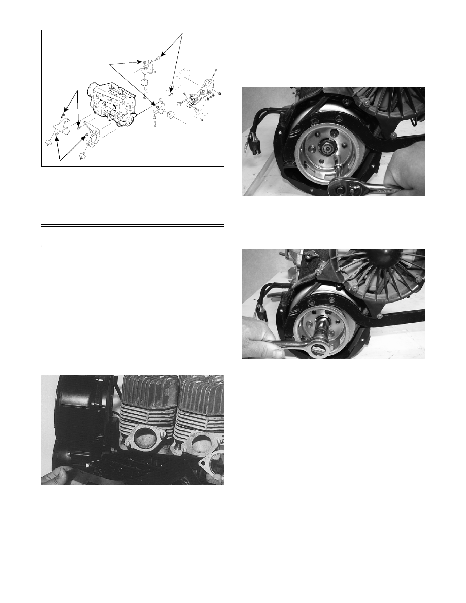
5. Remove the nuts securing the intake manifold;

then remove the manifold with flange from the

engine. Account for two insulators. Discard the

gaskets.

6. Remove the intake-manifold cooling shroud from

the engine. Discard the two gaskets.

7. Using Flywheel Spanner Wrench (p/n 0144-007)

to secure the crankshaft, remove the three cap

screws and lock washers securing the starter pul-

ley to the flywheel. Remove the starter pulley;

then carefully pry the fan belt drive pulley from its

seated position on the flywheel and remove.

MD2494

8. Temporarily install the starter pulley on the fly-

wheel with three cap screws. Using the flywheel

spanner wrench to secure the crankshaft, loosen

and remove the flywheel nut and washers.

MD2495

„NOTE: If an impact wrench is being used, use of
a flywheel spanner wrench will not be necessary.

9. Remove the cap screws securing the starter pulley

to the flywheel and remove the pulley.

10. Remove the flange nuts securing the fan case to

the crankcase; then remove the fan case.

„NOTE: For further servicing of the axial fan com-
ponents, see section 3.

2-23

2

AB015

11. Install a protective cap onto the end of the crank-

shaft.

„NOTE: A suitable protective cap can be made by
welding a 3 mm (1/8 in.) plate on one side of a
spare flywheel nut.

AB022

12. Using the Flywheel Puller (p/n 0744-040) or suit-

able equivalent, remove the flywheel from the

crankshaft by tightening the puller bolt, striking

the head of the puller bolt with a hammer, and

tightening again. Repeat procedure until the fly-

wheel is free. Account for the key in the end of the

crankshaft.

„NOTE: To ensure the cleanliness of the flywheel
magnets, place the flywheel (with the magnets fac-
ing upward) on a clean bench.

13. Scribe a reference line on the stator plate and

crankcase to aid in assembly; then remove the two

Allen-head cap screws, lock washers, and washers

securing the stator plate.

„NOTE: The two stator plate Allen-head cap
screws had Loctite applied to the threads during
assembly. Before removing them, apply a sharp
blow to the head of each screw to break the Loctite
loose. If this isn’t done, the screws can be very dif-
ficult to remove.

AB026

14. Remove the stator plate from the engine.

15. Remove the screws, lock washers, and washers

securing the oil-injection pump to the crankcase;

then remove the pump, retainer, shim, and gear.

Account for two gaskets.

AB018

16. Remove the spark plugs.

17. Remove the eight nuts, lock washers, and washers

securing the cylinder heads to the cylinders. Note

the position of the different-sized nuts. Remove

the heads and account for two gaskets and four

dowel pins.

B563

! CAUTION

To prevent damage to the crankshaft, thread a pro-
tective cap onto the crankshaft. The puller must bot-
tom on the cap and not on the crankshaft. Also, do
not thread puller bolts more than 12.7 mm (1/2 in.)
into the flywheel. Damage to the coils may result.

2-24

18. Using a rubber hammer, gently tap the cylinders

and remove from the crankcase by lifting them

straight up off their studs. Discard the two gaskets.

Account for two dowel pins.

19. Using a felt-tipped marker, mark an M on the

MAG-side head, cylinder, and piston and a P on

the PTO-side head, cylinder, and piston.

„NOTE: For proper assembly, keep all MAG-side
components and all PTO-side components sepa-
rated. Assemble them on their proper sides.

20. Remove the PTO-side piston-pin circlip from the

PTO-side piston; remove the MAG-side piston-pin

circlip from the MAG-side piston.

A829

21. Using the Piston-Pin Puller (p/n 0644-328),

remove the piston pins from both pistons.

A830

22. Lift the pistons clear of the connecting rods and

remove the small end connecting-rod bearings;

then remove the piston rings. Keep each piston

with its rings, piston pin, and bearing together as a

set.

„NOTE: Place rubber bands over the connecting
rods and around the cylinder studs. This will keep
the connecting rods from damaging the crank-
case.

B160

23. Remove the cap screws securing the crankcase

halves. Note the position of the different-sized cap

screws.

A831

24. Separate the crankcase halves by installing two

crankcase cap screws in diagonal corners leaving

the heads approximately 6 mm (1/4 in.) out. Using

a plastic hammer, tap on each cap screw head until

the halves separate. Remove the cap screws.

25. Remove the rubber bands holding the connecting

rods; then separate the crankcase halves. Account

for the two dowel pins. Lift the crankshaft free

from the crankcase half and slide the two crank-

shaft seals off the crankshaft. Account for the C-

ring and five bearing retaining pins.

! CAUTION

When removing a cylinder, make sure to support the
pistons so they will not be damaged.

! CAUTION

DO NOT use any type of punch to drive the piston
pin free of the piston; damage may result. Use a pis-
ton-pin puller only.

! CAUTION

DO NOT drive any tool between the crankcase
halves to separate the crankcase. Damage to the
sealing surfaces will result.

2-25

2

Cleaning and Inspecting 

Engine

„NOTE: Whenever a part is worn excessively,
cracked, or damaged in any way, replacement is
necessary.

CYLINDER HEAD

1. Using a non-metallic carbon removal tool, remove

any carbon buildup from the combustion chambers

being careful not to nick, scrape, or damage the

combustion chambers or the sealing surfaces.

2. Inspect the spark-plug holes for any damaged

threads. Repair damaged threads using a heli-coil

insert.

3. Place the cylinder heads on a Surface Plate (p/n

0644-016) covered with #400 grit wet-or-dry

sandpaper. Using light pressure, move each cylin-

der head in a figure eight motion. Inspect the seal-

ing surface for any indication of high spots. A high

spot can be noted by a bright metallic finish. Cor-

rect any high spots before assembly by continuing

to move the cylinder head in a figure eight motion

until a uniform bright metallic finish is attained.

MD2498

CYLINDERS

1. Using a non-metallic carbon removal tool, remove

carbon buildup from the exhaust ports.

2. Wash the cylinders in parts-cleaning solvent.

3. Inspect the cylinders for pitting, scoring, scuffing,

and corrosion. If marks are found, repair the sur-

face with an appropriate ball hone and honing oil

(see chart).

„NOTE: To produce the proper 60° crosshatch pat-
tern, use a low RPM drill (600 RPM) at the rate of 30
strokes per minute. If honing oil is not available,
use a lightweight, petroleum-based oil. Thoroughly
clean the cylinders after honing using detergent
soap and hot water and dry with compressed air;
then immediately apply oil to the cylinder bores. If
a bore is severely damaged or gouged, the cylin-
der will have to be replaced.

4. Place the head surface of each cylinder on the sur-

face plate covered with #400 grit wet-or-dry sand-

paper. Using light pressure, move each cylinder in

a figure eight motion. Inspect the surface for any

indication of high spots. A high spot can be noted

by a bright metallic finish. Correct any high spots

before assembly by continuing to move the cylin-

der in a figure eight motion until a uniform bright

metallic finish is attained.

PISTON ASSEMBLY

1. Using a non-metallic carbon removal tool, remove

the carbon buildup from the dome of each piston.

2. Take an old piston ring and snap it into two pieces;

then grind the end of the old ring to a 45° angle

and to a sharp edge. Using the sharpened ring as a

tool, clean carbon from the ring-grooves. Be sure

to position the ring with its tapered side up.

3. Inspect each piston for cracks in the piston pin and

skirt areas.

4. Inspect each piston for seizure marks or scuffing.

Repair with #400 grit wet-or-dry sandpaper and

water or honing oil.

! CAUTION

Water or parts-cleaning solvent must be used in
conjunction with the wet-or-dry sandpaper or dam-
age to the sealing surface may result.

BALL HONE

Engine Size

p/n

370 cc

0644-290

! CAUTION

Water or parts-cleaning solvent must be used in
conjunction with the wet-or-dry sandpaper or dam-
age to the sealing surface may result.

! CAUTION

Improper cleaning of the ring-grooves by the use of
the wrong type of ring-groove cleaner will result in
severe damage to the piston.


Content   ..  7  8  9  10   ..