Snowmobile Arctic Cat (2008 year). Manual - part 86


  Index      Snowmobiles / ATV     Snowmobile Arctic Cat - service manual 2008 year


Search            


Content   ..  84  85  86  87   ..


Snowmobile Arctic Cat (2008 year). Manual - part 86


5

5-25

AI034

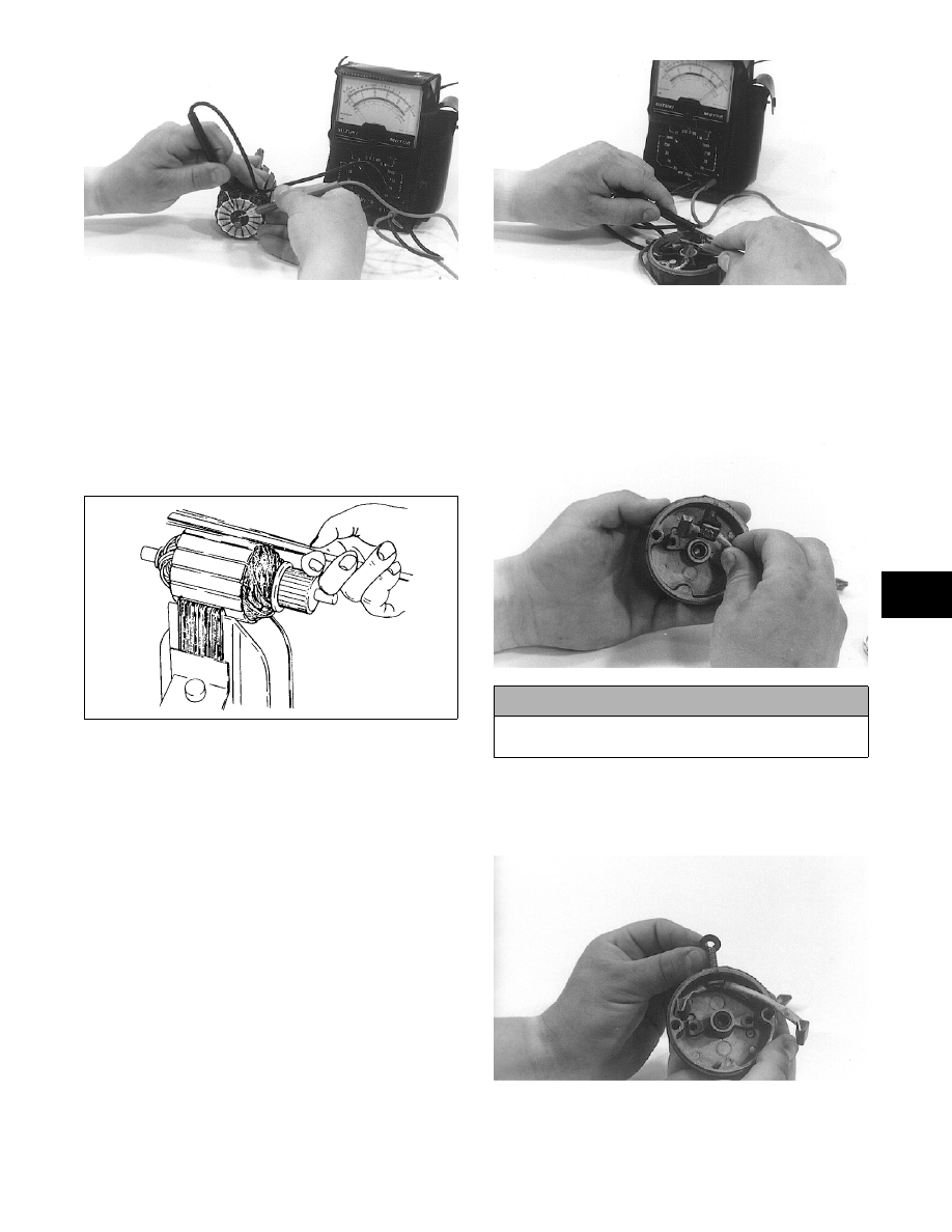
10. Inspect the armature for shorting. Use a “growler”

and the following procedure:

A. Place the armature in the “growler.”

B. While holding a metal strip over the armature,

rotate the armature an entire revolution. If the

metal strip vibrates at any point on the arma-

ture, the armature is shorted and must be

replaced.

0725-653

11. Inspect the ground brushes to make sure they are

properly grounded. Use the multitester and the fol-

lowing procedure:

A. Set the selector on the OHMS position; then

touch the leads and zero the meter.

B. Touch the black tester lead to a ground brush.

C. Touch the red tester lead to the commutator cap.

The meter needle should move to the right. If

the needle does not move to the right, check

that the ground connection is tight and clean.

Recheck for proper ground. If there still isn't

any meter needle movement, replace the

brushes as a set along with new brush springs.

AI035

ASSEMBLING

1. Install the stud with the positive brush set attached

in the commutator cap. Make sure the insulator is

in position over the stud and the longest brush lead

is positioned to the right of the stud hole.

AI038

2. In order from disassembling, place the washers on

the stud. Apply a small amount of red Loctite #271

to the stud threads and secure with the nut. Tighten

to 60 in.-lb.

AI039

3. Place the brush holder into position in the commu-

tator cap.

! CAUTION

Check the stud to make sure insulator is between
stud and cap on backside.

5-26

„NOTE: Position the longest positive brush lead
beneath the ground wire on right side.

4. Place a cap screw through the left ground brush

lead eyelet and position the eyelet flat against the

brush holder. Secure with a cap screw.

5. Place the right ground brush eyelet flat against the

brush holder and secure with a cap screw. The eye-

let stem must be positioned to the top of the

threaded hole boss in the commutator cap.

AI040

6. Place the four brush springs into the brush holder

and place each brush (flat side down) on top of the

springs.

„NOTE: Apply a small amount of low-temperature
grease to the cap bushings.

7. Place a wave washer and a thrust washer on the

armature shaft; then slide the front cap into position.

8. Apply a thin coat of grease to the armature shaft

and slide the drive gear and spring washer onto the

shaft. Secure with a snap ring.

9. Start the commutator end of the armature assem-

bly into the starter case at the end with the fields

nearest the end of the housing. Align the marks on

the front cap and case.

AI042

10. Compress the four brushes (flat side down) into

the brush holder. Hold the brushes in position

using the Starter Assembly Tool.

AI043

11. Carefully place the starter case and armature

assembly into the commutator cap. Again, check

to make sure the scribed marks of these two com-

ponents are aligned. With the case flat on the

assembly tool, slowly pull the tool from the starter

motor. The case should then drop into place.

AI044

12. Apply red Loctite #271 to the threads of the two

through-bolts; then install and secure the bolts.

Tighten to 8 ft-lb.

„NOTE: The starter shouldn’t be picked up until
the two through-bolts have been secured. Spring
pressure from the brush springs will push the
commutator cap off the case.

DISASSEMBLING PINION

1. Remove the dust cap from the end of the pinion

drive by first pulling straight out and then twisting

the dust cap to the side.

2. Place a 11 mm or a 7/16 in. socket over the end of

the pinion shaft and tap the socket gently with a

hammer.

„NOTE: This procedure will dislodge the snap-ring
retainer and expose the snap ring.

3. Using a side cutter, diagonal cutter, or suitable pli-

ers, remove and discard the snap ring.

4. Remove the snap-ring retainer (note end-for-end

orientation), pinion spring, spring retainer, and

pinion gear. Retain all components.

5

5-27

CLEANING AND INSPECTING 
PINION

„NOTE: Whenever a part is worn excessively,
cracked, or damaged in any way, replacement is
necessary.

1. Using parts-cleaning solvent, wash grease from

the pinion gear. Dry with compressed air.

2. Inspect the pinion gear for wear. If the gear is

worn or chipped, replace the pinion assembly.

3. Inspect the inner gear and housing. If the gear

shows any signs of wear, replace the pinion assem-

bly.

4. Inspect the inner housing for tightness and cracks.

If the housing shows any signs of being loose or

cracked, replace the pinion assembly.

5. Inspect the pinion return spring for wear. If the

spring shows any worn areas, replace the spring.

ASSEMBLING/INSTALLING PINION

1. Slide the pinion gear, spring retainer, pinion

spring, and snap-ring retainer (note end-for-end

orientation) onto the shaft in their original posi-

tions.

2. Place new snap ring over the end of the pinion

shaft; then slide the snap ring over the shaft. Using

a 11 mm or 7/16 in. socket and a hammer, gently

tap the snap ring into the groove on the shaft.

3. Slide the dust cover over the pinion assembly

being careful not to dislodge the grease. Firmly

push the dust cover until it snaps into its retaining

groove.

TESTING STARTER MOTOR

„NOTE: Before installing the starter motor, per-
form test to ensure proper operation using the fol-
lowing procedure.

1. Attach a black jumper cable to a good ground on

the starter.

2. Attach the opposite end of the black jumper cable

to the negative post of a good 12V battery.

3. Attach the red jumper cable to the positive post of

the battery.

4. Holding the starter firmly down on a work bench,

touch the red jumper cable to the positive cable

stud of the starter.

„NOTE: Starter motor must instantly spin at a high
RPM. The pinion must snap out against the stop-
per. If the motor does not spin, remove the red
cable immediately. Check the battery condition
and all connections. If everything checks out satis-
factorily and the starter does not spin, disassem-
ble the motor and check for pinched or broken
wires.

INSTALLING (Panther 370)

1. Place the starter motor into the bracket; then

secure with existing hardware. Tighten to 13 ft-lb.

2. Attach the red positive cable to the positive stud

terminal and secure with a nut and washers. While

tightening the nut, hold the cable in position so it

is parallel with the starter.

3. Secure the positive cable to the starter motor with

a long cable tie.

4. Connect the cable to the positive post of the bat-

tery; then connect the negative cable to the nega-

tive post.

5. Install the drive clutch.

6. Install the expansion chamber.

INSTALLING (Bearcat 570)

1. Install the flex-drive shaft onto the starter motor

and secure with the two Allen-head screws.

2. Place the starter motor into the bracket assembly;

then secure with existing hardware. Tighten to 17

ft-lb.

3. Attach the red positive cable to the positive stud

terminal and secure with a nut and washers. While

tightening the nut, hold the cable in position so it

is parallel with the starter.

! WARNING

When using compressed air to dry components,
always wear safety glasses.

! WARNING

Be sure to keep clear of the pinion gear area as it will
spin at a high RPM when the red cable is touched to
the positive stud. Personal injury may result if con-
tact is made with a spinning pinion.

! CAUTION

Check the cable installation to make sure it isn’t
near any moving parts or against any sharp edges.

! CAUTION

Check the cable installation to make sure it isn’t
near any moving parts or against any sharp edges.

5-28

INSTALLING (F 570/T570)

1. With the rubber dampers in place on the brackets,

install the starter motor and the MAG-side bracket

to the engine with the two cap screws and tighten

to 20 ft-lb. Route the positive lead up through the

engine plate and secure with cap screw. Tighten

securely.

„NOTE: Make sure the rubber exhaust bumper is
in position on the close-off cover before installing
the expansion chamber.

2. Place gaskets on the resonator and exhaust mani-

fold; then install the expansion chamber. Secure

the chamber to manifold and upper frame with the

springs.

„NOTE: When installing the exhaust manifold
springs, the long hook portion of the spring must
be attached to the exhaust manifold or premature
spring failure will result.

3. Connect the battery.

INSTALLING (500/600 LXR cc 
Models)

1. Install the mounting bracket to the starter motor;

then secure with existing hardware. Tighten

securely.

2. Place the flex-drive shaft into position on the pin-

ion driveshaft so the set screws are aligned with

the flat-side of the pinion driveshaft; then tighten

the set screws (coated with blue Loctite #243)

securely.

3. Place the mounting bracket/starter motor into posi-

tion and secure to the chassis with the lock nuts.

4. Attach the battery cables to the starter motor and

secure with nuts.

5. Connect the battery cables (positive cable first) to

the battery.

INSTALLING 

(800/1000 cc LXR Models)

1. Install the mounting bracket to the starter motor;

then secure with existing hardware. Tighten

securely.

2. Place the flex-drive shaft into position on the pin-

ion driveshaft so the set screws are aligned with

the flat-side of the pinion driveshaft; then tighten

the set screws (coated with blue Loctite #243)

securely.

FS204

3. Place the starter motor with brackets into position

on the chassis and upper frame; then secure with

the cap screws and lock nuts. Tighten securely.

„NOTE: For installing purposes, it may be neces-
sary to loosen the lock nut securing the bracket to
the starter motor.

4. Place the positive and negative cables on the

starter motor; then secure with the lock nuts.

Tighten securely.

FS205A

5. Connect the battery cables (positive cable first) to

the battery.

6. Install and secure the resonator and the expansion

chamber.

„NOTE: To finalize the installing procedure, the air
silencer must be installed. Proceed to the appro-
priate Air-Intake Silencer sub-section in Section 4.


Content   ..  84  85  86  87   ..