Snowmobile Arctic Cat (2008 year). Manual - part 82
5
5-9
AK013
4. Charge coil (2) resistance must be between 7.20-
10.8 ohms.
LIGHTING COIL
1. Disconnect the main wiring harness from the
engine.
2. Set the selector in the OHMS position.
3. Connect the two meter leads to each of the yellow
leads in the connector from the engine.
AK015
4. Lighting coil resistance must be between 0.08-
0.12 ohm.
IGNITION TIMING SENSOR
1. Disconnect the timing sensor connector (green/
white and brown/green) from the ECU.
2. Set the selector in the OHMS position; then con-
nect the meter leads to the sensor leads.
3. Ignition timing sensor resistance must be between
148-222 ohms (500 cc) or 80.8-121 ohms (600 cc).
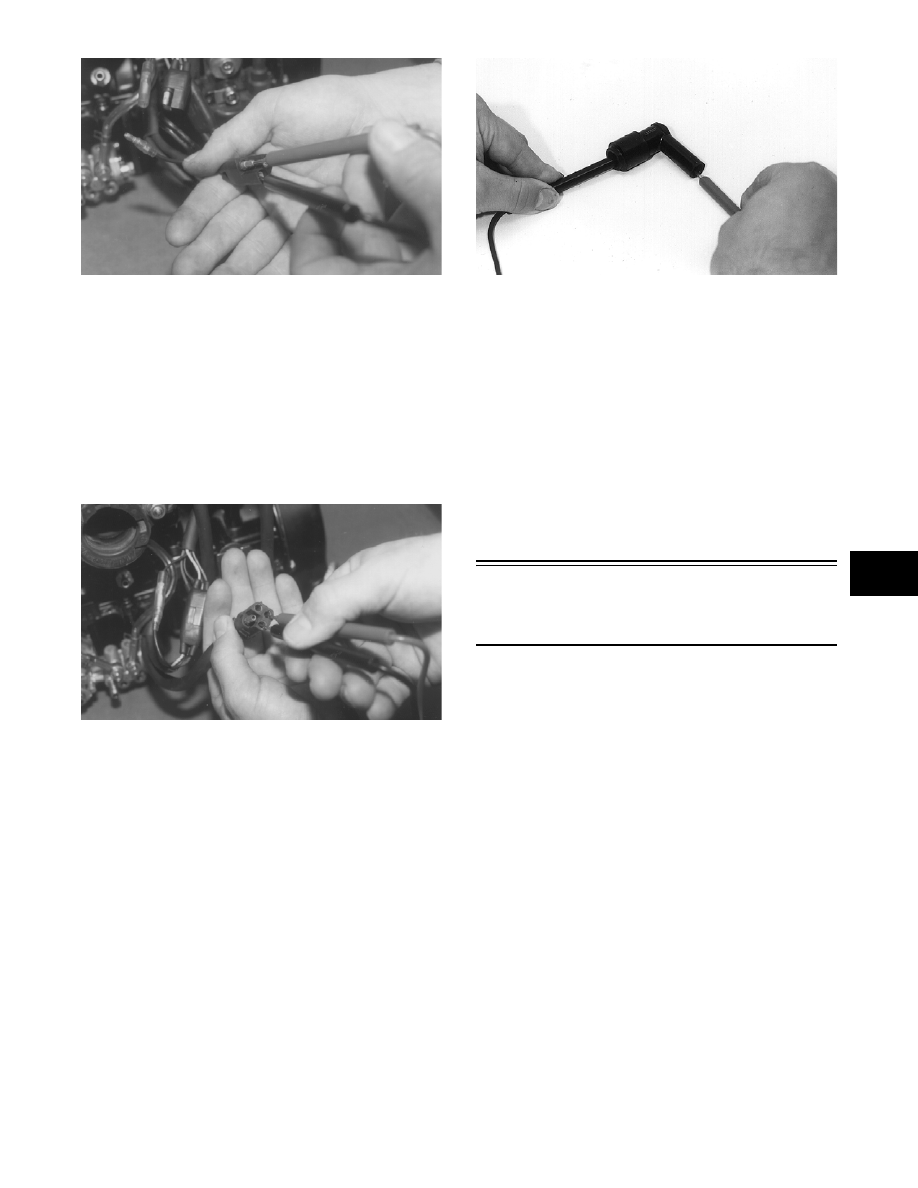
SPARK-PLUG CAP
1. Remove the spark-plug caps from the high tension
wires.
2. Set the selector in the OHMS position.
3. In turn on each cap, touch a tester lead to each end
of the spark-plug cap.
B170
4. Spark-plug cap resistance must be between 4000-
6000 ohms.
IGNITION SWITCH
1. Remove the main wiring harness connectors from
the ignition switch.
2. Rotate the key to the OFF position.
3. The meter must read less than 1 ohm resistance
between the ignition switch terminals.
4. Rotate the key to the RUN position.
5. The meter must read OL (infinite resistance).
Testing Electrical
Resistances
(800/1000 cc Models)
NOTE: Resistance tests of the engine electrical
components should be made using the Fluke Mul-
timeter only. Analog-style multitesters may not be
accurate enough to use in these critical tests.
Replace any component that does not have a test
value within specifications.
IGNITION COIL (Primary)
1. Disconnect the double wire plug from the ECU to
the ignition coil.
2. Set the selector in the OHMS position.
3. Connect the red meter lead to the black/white lead;
then connect the black meter lead to the white/blue
lead.
4. Ignition coil primary resistance must be between
0.24-0.36 ohm.
IGNITION COIL (Secondary)
1. Remove the spark-plug caps from the high tension
wires.
2. Set the selector in the OHMS position.