Snowmobile Arctic Cat (2008 year). Manual - part 50


  Index      Snowmobiles / ATV     Snowmobile Arctic Cat - service manual 2008 year


Search            


Content   ..  48  49  50  51   ..


Snowmobile Arctic Cat (2008 year). Manual - part 50


2-138

FC034

25. Lift the bottom half of the crankcase off the top

half.

26. Lift the crankshaft free from the top half of the

crankcase and slide the crankshaft oil seals off the

crankshaft. Account for the C-ring. Remove the

bearing retaining pins and account for the crank-

case dowel pins.

„NOTE: The end bearings are not pressed onto
the crankshaft. After removing the seals, use care
not to allow the bearings to slide off the crank-
shaft.

27. Remove the oil-injection pump/water pump drive-

shaft from the lower crankcase half. Account for

the thrust washer on the outer end of the shaft.

FC035

„NOTE: Do not replace the inner seals unless the
water pump shows signs of leaking coolant out of
the small bleed hole in the bottom half of the
crankcase. If a water pump seal is to be replaced,
use the Water Pump Bearing and Seal Kit.

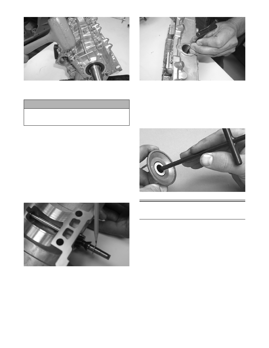
28. Place the crankcase on the bench with the water

pump side down. Using the long seal driver, drive

the mechanical water pump seal from the crank-

case.

FC036

29. Using a pair of snap ring pliers, remove the snap

ring securing the inner seal in the crankcase.

30. Using the hooked end of the tool, pull the inner

seal free of the crankcase.

31. Using the hooked end of the tool, pry the seal ring

from the backside of the water pump impeller.

AN327D

Cleaning and Inspecting 

Engine

„NOTE: Whenever a part is worn excessively,
cracked, or damaged in any way, replacement is
necessary.

CYLINDER HEAD

1. Using a non-metallic carbon removal tool, remove

any carbon buildup from the combustion chambers

being careful not to nick, scrape, or damage the

combustion chambers or the sealing surfaces.

2. Inspect the spark-plug holes for any damaged

threads.

3. Inspect the cylinder head for flatness using a

straightedge and a feeler gauge. Acceptable

warpage must not exceed 0.05 mm (0.002 in.).

! CAUTION

Care must be taken to not allow the connecting rods
to drop onto the sealing surface of the bottom case
half.

2-139

2

„NOTE: If the warpage exceeds specification,
resurface the cylinder head using procedures
identified in step 4.

FS270

4. Place the cylinder heads on a Surface Plate cov-

ered with #400 grit wet-or-dry sandpaper. Using

light pressure, move each cylinder head in a figure

eight motion. Inspect the sealing surface for any

indication of high spots. A high spot can be noted

by a bright metallic finish. Correct any high spots

before assembly by continuing to move the cylin-

der head in a figure eight motion until a uniform

bright metallic finish is attained.

CM018

CYLINDERS

1. Using a non-metallic carbon removal tool, remove

carbon buildup from the exhaust ports.

2. Wash the cylinders in parts-cleaning solvent.

3. Inspect the cylinders for pitting, scoring, scuffing,

and corrosion. If marks are found, repair the sur-

face with a Ball Hone and honing oil.

„NOTE: To produce the proper 45° crosshatch
pattern, maintain a low drill RPM. If honing oil is
not available, use a lightweight, petroleum-based
oil. Thoroughly clean the cylinders after honing
using detergent soap and hot water and dry with
compressed air; then immediately apply oil to the
cylinder bores. If a bore is severely damaged or
gouged, the cylinder will have to be replaced.

4. Place the head surface of each cylinder on the sur-

face plate covered with #400 grit wet-or-dry sand-

paper. Using light pressure, move each cylinder in

a figure eight motion. Inspect the surface for any

indication of high spots. A high spot can be noted

by a bright metallic finish. Correct any high spots

before assembly by continuing to move the cylin-

der in a figure eight motion until a uniform bright

metallic finish is attained.

PISTON ASSEMBLY

1. Using a non-metallic carbon removal tool, remove

the carbon buildup from the dome of each piston.

2. Take an old piston ring and snap it into two pieces;

then grind the end of the old ring to a 45° angle

and to a sharp edge. Using the sharpened ring as a

tool, clean carbon from the ring-grooves. Be sure

to position the ring with its tapered side up.

3. Inspect each piston for cracks in the piston pin and

skirt areas.

4. Inspect each piston for seizure marks or scuffing.

Repair with #400 grit wet-or-dry sandpaper and

water or honing oil.

AN135

! CAUTION

Water or parts-cleaning solvent must be used in
conjunction with the wet-or-dry sandpaper or dam-
age to the sealing surface may result.

! CAUTION

Water or parts-cleaning solvent must be used in
conjunction with the wet-or-dry sandpaper or dam-
age to the sealing surface may result.

! CAUTION

Improper cleaning of the ring-grooves by the use of
the wrong type of ring-groove cleaner will result in
severe damage to the piston.

2-140

„NOTE: If scuffing or seizure marks are too deep
to correct with the sandpaper, it will be necessary
to replace the piston.

5. Inspect the perimeter of each piston for signs of

excessive “blowby.” Excessive “blowby” indicates

worn piston rings or an out-of-round cylinder.

„NOTE: If synthetic oil is being used, a certain
amount of “blowby” may be visible under normal
use.

CRANKCASE

1. Wash the crankcase halves in parts-cleaning sol-

vent.

„NOTE: Before washing the crankcase halves,
make sure the four bearing dowel pins have been
removed and accounted for.

2. Inspect the crankcase halves for scoring, pitting,

scuffing, or any imperfections in the casting.

3. Inspect all threaded areas for damaged or stripped

threads.

4. Inspect the bearing areas for cracks or excessive

bearing movement. If evidence of excessive bear-

ing movement is noted, the crankcase must be

replaced.

5. Inspect the bearing dowel pins for wear.

6. Inspect the sealing surfaces of the crankcase

halves for trueness by placing each crankcase half

on the surface plate covered with #400 grit wet-or-

dry sandpaper. Using light pressure, move each

half in a figure eight motion. Inspect the sealing

surfaces for any indication of high spots. A high

spot can be noted by a bright metallic finish. Cor-

rect any high spots by continuing to move the half

in a figure eight motion until a uniform bright

metallic finish is attained.

„NOTE: Care must be taken not to remove an
excessive amount of aluminum, or the crankcase
will have to be replaced. If excessive aluminum is
removed, too much pre-load will be exerted on the
crankshaft bearings when assembled.

CM160

CRANKSHAFT

„NOTE: If any servicing of the connecting rods,
center bearings, or oil-injection pump drive gear is
necessary, Arctic Cat recommends that the crank-
shaft be taken to a qualified machine shop for that
service.

1. Wash the crankshaft with bearings in parts-clean-

ing solvent.

2. Inspect the bearings for wear, scoring, scuffing,

damage, or discoloration. Rotate the bearings.

Bearings must rotate freely and must not bind or

feel rough. If any abnormal condition is noted,

replace the bearing.

FC039

3. Inspect the connecting-rod bearings by rotating

them. The bearings must rotate freely and must not

bind or feel rough. If a connecting-rod bearing

must be replaced, the connecting rod and crank pin

must also be replaced.

FC040

4. Inspect the oil-injection pump drive gear for any

signs of worn or chipped teeth. If either condition

exists, replace the gear.

„NOTE: Lubricate bearings thoroughly prior to
assembly.

! CAUTION

Water or parts-cleaning solvent must be used in
conjunction with the wet-or-dry sandpaper or dam-
age to the sealing surface may result.

2-141

2

REMOVING/INSTALLING OUTER 
CRANKSHAFT BEARINGS

„NOTE: The end bearings are not pressed onto
the crankshaft. The bearings can be removed sim-
ply by sliding them off the crankshaft.

CM161

„NOTE: Install the bearings by sliding each bear-
ing onto the crankshaft making sure the dowel-pin
hole in the outer race is properly positioned and
will align with its hole and pin in the crankcase.

CM161

REED VALVE ASSEMBLY

1. Inspect the reed valves, stoppers, and valve blocks

for cracks or any deterioration.

CM162

2. Wash the reed valves, stopper, and cage assembly

in parts-cleaning solvent and blow dry.

3. Inspect the reed stopper height. Using a caliper,

measure the distance from the seat to the bottom

outer tip edge of the stopper. Measurement must

not exceed specifications. If measurement is not

within specifications, either bend or replace the

reed stopper.

CM163

4. Inspect the reed-to-seat clearance. Using a feeler

gauge, measure the clearance. Clearance must be

less than 0.20 mm (0.008 in.). If clearance is not

within specifications, replace the reed valve.

5. To assemble, place the reed valves on the cage

with its clipped corner positioned to the lower

right hand corner of the cage. Place the reed stop-

per assembly into position and secure with the

screws coated with red Loctite #271.

CM164A

Measuring Critical 

Components

„NOTE: Critical engine specifications charts can
be found in Section 1 of this manual.

CYLINDER HEAD VOLUME 
(Squish-Gap Method)

To check the squish gap, a micrometer and two heavy

pieces of solder will be needed.

1. Remove the spark plugs from the engine.


Content   ..  48  49  50  51   ..