Snowmobile Arctic Cat (2007 year). Manual - part 97


  Index      Snowmobiles / ATV     Snowmobile Arctic Cat - service manual 2007 year


Search            


Content   ..  95  96  97  98   ..


Snowmobile Arctic Cat (2007 year). Manual - part 97


9

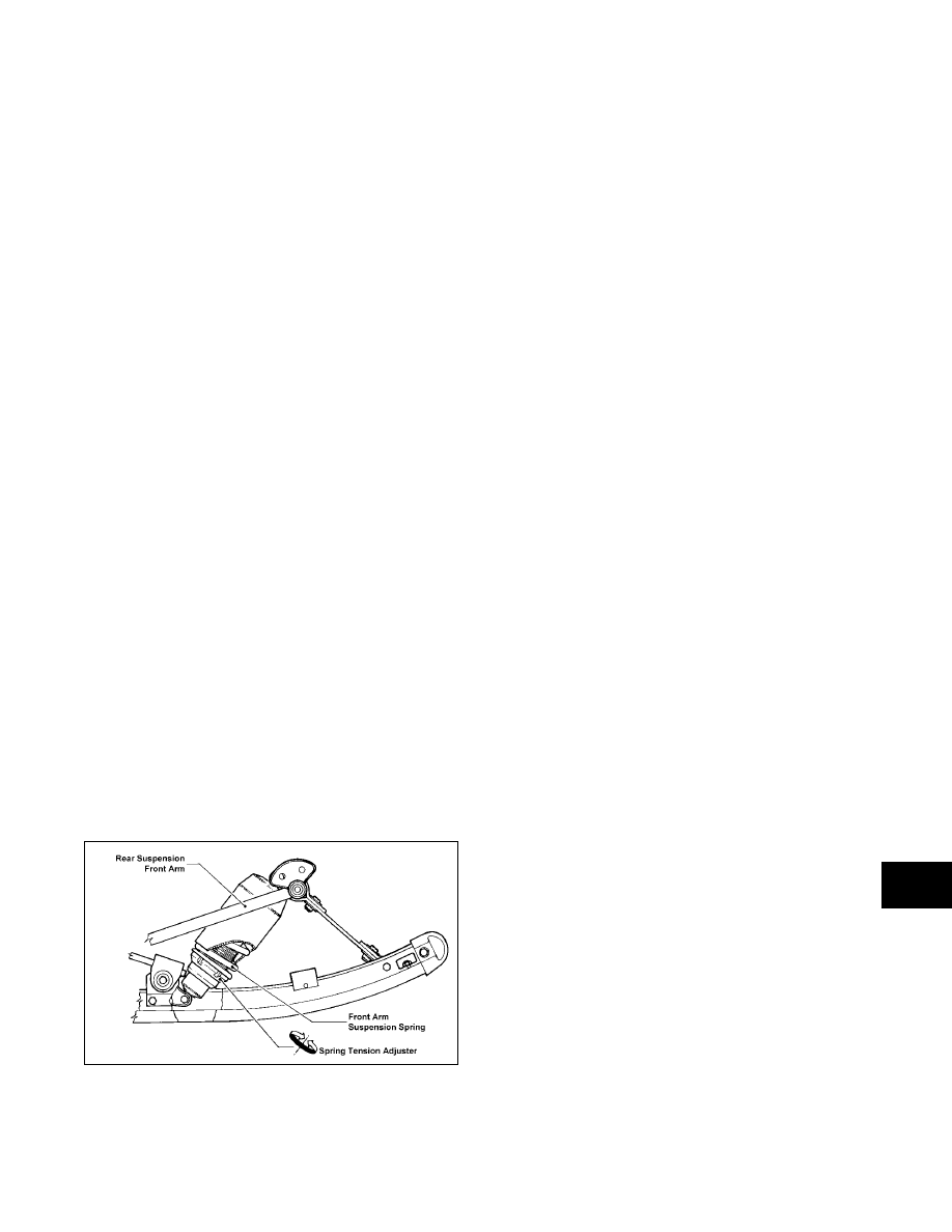
SUSPENSION SETUP BASICS

FRONT ARM SPRING TENSION

„ NOTE: Read the following information closely as
it pertains to all suspensions used in the last sev-
eral years. If there are any questions, please con-
tact the Arctic Cat Service Department.

It is desirable to run with very light front arm spring

tension. When riding in 4 in. or more of snow, the

machine will be quicker if the front spring tension is

adjusted lightly.

If the spring tension is adjusted too stiff, the track

angle at the front of the skid frame is steep. This

steep angle prevents the snowmobile from getting

up on plane and slows down by 5 to 8 mph.

When riding in sticky snow (springtime or warm

days) or hill climbing on hard snow, it may be desir-

able to stiffen the front arm spring tension. When

this is done, weight is transferred back quicker. The

problem with too much front arm spring tension is

that the feel of the snowmobile becomes very short.

The reason for this is the front arm becomes the

pivot point between the spindles and rear of the

machine. With dominant spring tension on the front

arm, the suspension is basically contacting the snow

from a point below the front arm to the skis or the

spindle pressure point. This makes for a very short

and darting machine on the trail. This is especially

true when decelerating and the center of gravity is

transferred forward.

A good method for adjusting the front spring tension

follows.

„ NOTE: On those models having a coil spring
over the front arm shock absorber, the spring ten-
sion should be set as soft as possible when oper-
ating on trails and in deep snow.

0729-662

FRONT ARM LIMITER STRAPS

Under no circumstances should the front arm limiter

strap be lengthened. If lengthened, it may cause

shock absorber travel problems.

The two limiter straps can be shortened if desired.

This adjustment must be made to suit driving style

and some test driving time. With the rear arm in its

present mounting location, no advantage has been

noted from changing the strap length. If the front

arm straps are shortened, the result will be more ski

pressure and aggressive steering.

SKI SHOCK ABSORBER SPRINGS

The shock absorber springs have been matched to

the shock valving and rear suspension. These

springs are the result of hours of testing and compar-

ison riding trying many different combinations of

springs and shocks. If there is a need to make

changes, there are several spring and shock sizes to

choose from. While making these changes, keep the

following points in mind.

Heavier Or Stiffer Springs

1. These will require shocks with more rebound

control, or the front end will become like a pogo

stick.

2. With stiffer springs, the front end will become

more aggressive in the corners as more weight

will be transferred to the skis when decelerating.

Also, more weight is transferred to the rear on

acceleration and can cause the rear shocks and

spring to bottom out.

3. If the springs are too stiff for general riding con-

ditions and style, the ride comfort is gone.

Spring Tension Too Soft

1. Front end bottoms out; hard on front end parts.

2. Less aggressive steering in corners on decelera-

tion, and less weight is transferred to the skis

because of softer springs.

3. Less weight gets transferred to rear of the

machine upon acceleration.

9-4

„ NOTE: When softening the ski springs, also
soften the rear to match entire suspension.

FRONT ARM SPRING TENSION 
TOO STIFF

1. Slows machine down in loose snow.

2. Causes the machine to dart and dive as a result

of less ski pressure on the ground during decel-

eration.

„ NOTE: It has been our experience that a tight
front arm works well under only two conditions:
sticky snow conditions in the spring of the year
and in hill climbing on hard packed snow.

It has also been our experience with AFS models

that with the front arm adjusted too soft, the spring

may come off the roller. There haven't been any

other problems in handling caused by a soft front

arm.

REAR ARM SPRING TENSION

The rear spring tension is adjusted for the weight of

the driver. There are three possible adjustments.

1st block position - set for up to 150 lb

2nd block position - set for 150 to 200 lb

3rd block position - set for over 200 lb

727-720A

REAR ARM MOUNTING POSITION
(Between Rails)

There are several mounting holes found in the rails

for installing the rear arm.

The holes have been added to the suspension to pro-

vide adjustment to fine-tune the suspension to driv-

ing styles.

If the ride is too soft, moving the rear arm back

between the rails will stiffen the ride. By moving the

rear arm forward, it will collapse quicker and allow

more transfer of weight to the back of the suspen-

sion. This will also affect the handling by providing

a softer ride and also easier steering.

The drawbacks of moving the rear arm forward are

that the suspension may bottom out quicker and

some travel is lost.

„ NOTE: When making any changes to the front or
rear suspension, the change should be made at
both ends to keep the suspension balanced. For
example, installing stiffer springs in front may
require installing the next step stiffer spring in
back to keep everything in balance.

ADJUSTING REAR ARM COUPLER

„ NOTE: The couplers are installed in the 2-groove
position at production.

The rear arm coupler provides advantages over the

standard suspension.

First, with the coupler system, ski lift under acceler-

ation is greatly reduced which provides improved

handling. Second, when riding through rough ter-

rain, the rear suspension arm receives some needed

assistance from the front arm shock and spring. This

happens as the rear arm is fully collapsed and locked

up by the coupler blocks. The front arm then starts

to collapse the shocks and spring which assist the

rear springs. The result is a smoother ride for the

operator.

Each of the coupler blocks has four positions

(notched grooves on the outside surface of the

block). When changing the block position, change

both to the same groove number. To make coupler

adjustment, follow the procedure below. 

1. Using a 9/16-in. wrench, loosen the two cap

screws that secure the coupler blocks to the

inside of the suspension rails.

2.  Rotate the coupler blocks to the desired position

making sure both are set the same.

! CAUTION

If the ski shock spring is adjusted too loose, the
spring retainer may fall out. If the spring is adjusted
beyond specification, the spring will coil bind and
spring adjuster damage will occur.

9-5

9

738-230B

„ NOTE: When setting the block, the chosen groove
position must be directed toward the idler arm.

738-230C

3. Place a 4-in. block of wood under the rear of the

suspension just in front of the rear idler wheels.

This will assist in collapsing the suspension.

4.  Collapse the rear suspension until the rear arm is

firmly against the coupler blocks. This will align

the two blocks squarely with the arm. While in

this position, tighten the two cap screws secur-

ing the blocks. 

SUSPENSION MOUNTING LOCATION CHART

„ NOTE: The Rear Arm Mounting Position refers to where the rear arm mounts into the tunnel. The Rear
Arm To Rail Position refers to where the lower portion of the rear arm mounts between the slide rails.

* w/Torque Sensing Link
** Some Bearcat Wide Track Turbo snowmobiles were manufactured w/articulating skid frame.

MODEL

TRACK 

LENGTH & LUG 

HEIGHT

SKID FRAME

FRONT ARM 

MOUNTING 

POSITION

REAR ARM 
MOUNTING 

POSITION

REAR ARM TO 

RAIL 

POSITION

SHOCK 

LINK ROD 

LENGTH

T660 Turbo Trail
Panther 660 Trail

15" x 121" x 1.25"
15" x 121" x 0.85"

Fastrack—Stamped 

Rail*

Upper

Above

Running Board

Second 

Hole Back

11.750 in.

(298.45 mm)

T660 Touring/Turbo 
Touring/Panther 660 
Touring

15" x 136" x 1.00"

Fastrack—Stamped 

Rail*

Upper

Above

Running Board

No Adjustment

11.750 in.

(298.45 mm)

Bearcat Wide Track
(Non-Turbo)

20" x 156" x 1.00" Fastrack—Formed Rail

Articulating

Lower

Below 

Running Board

Second 

Hole Back

11.750 in.

(298.45 mm)

Bearcat Wide Track 
Turbo**

20" x 156" x 1.25"

Fastrack—Stamped 

Rail*

Upper

Above

Running Board

No Adjustment

11.750 in.

(298.45 mm)

Jaguar Z1

15" x 121" x 1.00"

Fastrack—Stamped 

Rail*

Upper

Above

Running Board

No Adjustment

11.750 in.

(298.45 mm)

9-6

Servicing Chart

This chart is designed to direct the technician to the

appropriate Skid Frame Schematics and Repair Pro-

cedure for servicing the rear suspension. Select the

snowmobile model from the list and follow the chart

to attain schematic designation and repair proce-

dure.

*Some Bearcat W/T Turbo snowmobiles were manufactured w/articulating skid frame.

Snowmobile Models

Slide 

Rail 

Style

Front 

Arm 

Style

Rear 

Arm 

Style

Idler 

Wheels 

Style

Articulating 

Skid Frame 

Style

Skid Frame 

Mounting 

Style

 Repair 

Procedure

Bearcat W/T (Non-Turbo)

E

C

D

B

G

C

2

Bearcat W/T Turbo

F

C

D

C*


N/A*

D

2

Panther 660/T660 Touring

D

B

B

E

N/A

B

2

Panther 660 Trail

C

B

C

D

N/A

A

3

T660 Turbo Touring

D

A

B

E

N/A

B

2

T660 Turbo Trail

B

A

E

D

N/A

A

3

Jaguar Z1

H

D

F

F

N/A

E

4

AC 120

A

N/A

A

A

N/A

N/A

1


Content   ..  95  96  97  98   ..