Snowmobile Arctic Cat (2007 year). Manual - part 9


  Index      Snowmobiles / ATV     Snowmobile Arctic Cat - service manual 2007 year


Search            


Content   ..  7  8  9  10   ..


Snowmobile Arctic Cat (2007 year). Manual - part 9


2-21

2

MD1422

11. Remove the hairpin clip securing the hood cable

to the hood. Remove the two pivot cap screws at

the front of the  hood; then remove the hood.

„ NOTE: It is not necessary to remove the hood to
remove the engine; however, it does allow for eas-
ier removal with less risk of damaging the hood.

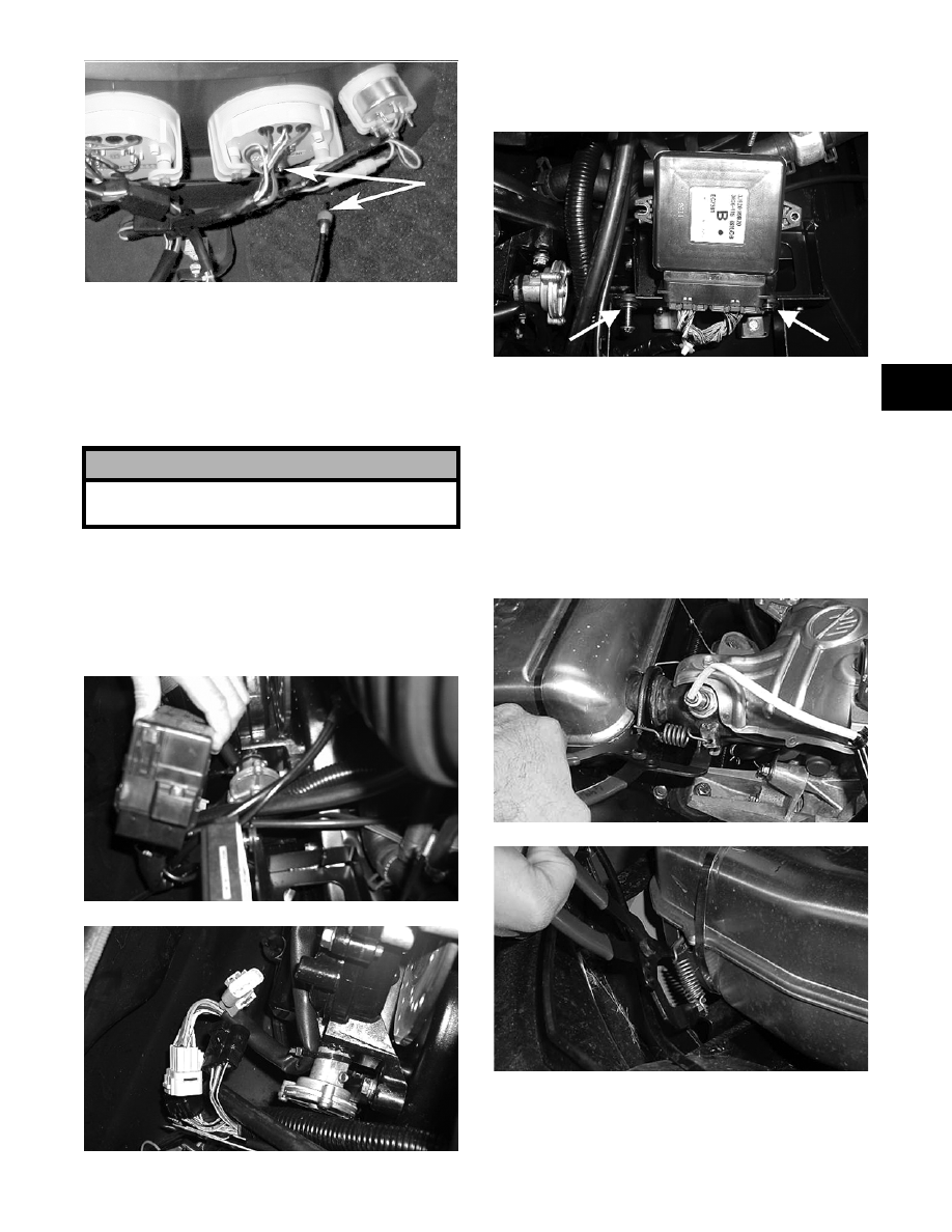
12. Pull out on the locking tabs and remove the fuse

block; then disconnect the main harness connec-

tors in the chassis.

„ NOTE: On turbo models, the fuse block is
located near the steering support.

AO183

AO185

13. Remove the two #27 torx-head cap screws

securing the ECU to the bracket; then remove

the ECU.

AO184A

14. On the non-turbo models using Exhaust Spring

Pliers (p/n 0644-391) or (p/n 0644-397), remove

the two springs securing the muffler to the

exhaust manifold. Remove the two springs

securing the muffler to the muffler support

brackets; then slide the muffler up out of the

chassis. Account for the grafoil gasket.

„ NOTE: On turbo models, remove the intercooler
(see Section 3); then remove the five exhaust
springs and remove the exhaust pipe.

AO267

AO180

„ NOTE: Do not loosen or remove the throttle from
the bracket.

! CAUTION

Take care not to damage the windshield when
removing the hood.

2-22

15. Remove the 6 mm cap screws securing the throt-

tle cable bracket to the intake plenum; then

remove the throttle body cable end from the

throttle body.

AO189

16. Remove the air silencer (see appropriate Servic-

ing Air Silencer in Section 3).

17. Remove the fuel line clamp at the fuel filter;

then remove the throttle body heater line clamp

from the main return coolant line and remove

the two hoses.

„ NOTE: Use caution; the fuel line may be under
pressure.

AO188

18. Remove the small hairpin clip and large hitch-

pin securing the belt guard in place; then remove

the belt guard. Account for two plastic collars.

„ NOTE: On turbo models, remove the flange nuts
securing the intercooler bracket to the engine;
then remove the bracket.

MD1563

MD1562

19. On the non-turbo models, remove the drive belt.

MD1732

„ NOTE: On the Bearcat W/T models, first loosen
the belly pan assembly from the footrest bracket;
then with the drive belt in the driven pulley only,
open the sheaves allowing the drive belt to go into
the driven pulley. The belt will be removed with the
driven pulley.

20. On turbo models, remove the drive belt using

the following procedure:

A. Remove the driven pulley plug from the belly

pan.

2-23

2

B. Using the Drive Belt Deflection Tool (p/n

0644-412), remove the sheave adjuster from

the end of the driven pulley. Account for and

remove the O-ring and shim washers. Note

the orientation of the components for install-

ing purposes.

„ NOTE: The sheave adjuster has left-hand
threads.

739-266B

C. With the O-ring and shim washers removed,

carefully thread the sheave adjuster back into

the driven pulley; then tighten the adjuster

with the deflection tool until it bottoms

against the driven shaft.

„ NOTE: By bottoming the sheave adjuster against
the driven shaft, the sheaves of the driven pulley
will spread far enough to allow the removal of the
drive belt.

D. Remove the drive belt from the drive clutch

and driven pulley.

739-267B

21. Remove the plug from the left side of the belly

pan.

22. Using a 1/2 in. 12-point socket, remove the cap

screw and lock washer securing the drive clutch

to the PTO adapter; then using Clutch Puller (p/

n 0644-207) and a breaker bar and Drive Clutch

Spanner Wrench (p/n 0644-136), tighten the

puller. If the drive clutch will not release,

sharply strike the head of the puller. Repeat this

step until the drive clutch releases. Remove the

drive clutch.

MD2485

23. On the non-turbo models, remove the cap screw

and washer securing the driven pulley; then

slide the driven pulley off the driven shaft.

Account for a key, stub shaft, and any alignment

washers.

„ NOTE: On the non-turbo Bearcat W/T, the drive
belt will come off with the pulley.

MD1707

24. On turbo models, remove the driven pulley

using the following procedure:

A. Remove the sheave adjuster from the end of

the driven pulley.

„ NOTE: The sheave adjuster has left-hand
threads.

B. Using a 9/16-in. socket and extension,

remove the cap screw securing the driven

pulley to the driven shaft.

2-24

„ NOTE: After removing the driven pulley, retrieve
the cap screw washer from inside the pulley bore;
then account for and remove any alignment wash-
ers. These washers must be used during installing.

AO372

25. Remove the two cap screws securing the starter

motor; then remove the starter motor.

MD1437

„ NOTE: On the Bearcat W/T models, first remove
the coolant hose from the filler neck housing to the
heat exchanger.

AO182

26. Remove the starter solenoid connector and

starter motor cable.

MD1700

27. Remove the two rear engine mount nuts; then

remove the two front engine mount cap screws.

AO190

AO199

28. Remove the hose clamp from under the coolant

filler cap housing and remove the hose; then

remove the overflow tank hose from the filler

cap housing.

„ NOTE: Secure the coolant overflow tank to pre-
vent it from draining.


Content   ..  7  8  9  10   ..