Snowmobile Arctic Cat (2004 year). Manual - part 146
9-100
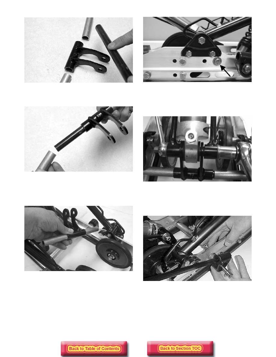
FC189
5. Slide the spacers onto the axle from each side of
the pivot.
FC190
6. Lower the pivot assembly down between the rails;
then align the axle with the mounting hole just
below and forward of the front arm mounting
brackets.
FC186
FC254C
7. Secure the shock rod links (with axles) and the
lower end of the shock absorber to the pivot
assembly with the cap screw and lock nuts.
Tighten to 4.2 kg-m (30 ft-lb).
FC188
8. Place the spring into the slide block; then place the
spring and slide block assembly into position on
the slide rail and rear arm. Secure with a cap screw
and washer. Tighten to 4.7 kg-m (34 ft-lb).
FC158