Snowmobile Arctic Cat (2004 year). Manual - part 137


  Index      Snowmobiles / ATV     Snowmobile Arctic Cat - service manual 2004 year


Search            


Content   ..  135  136  137  138   ..


Snowmobile Arctic Cat (2004 year). Manual - part 137


9-64

AG467D

AG553D

„

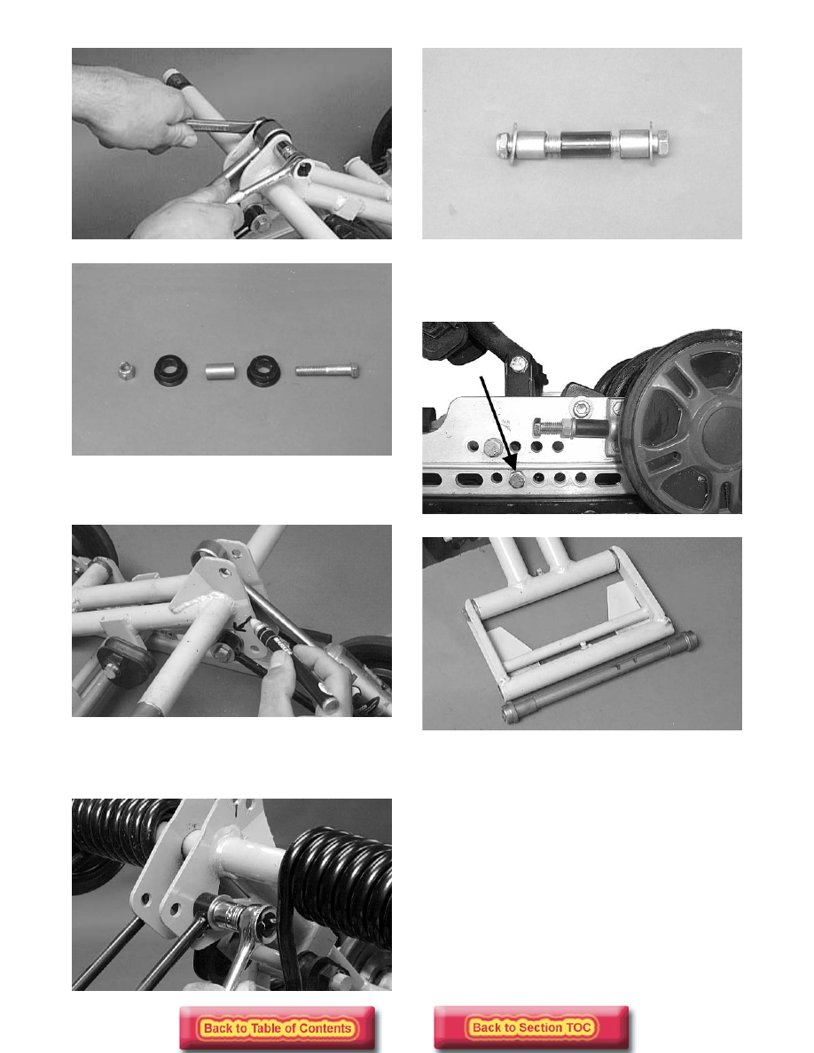
NOTE: Mark the hole that the upper shock links

are mounted in for assembly purposes.

AG554D

3. Remove the cap screw and lock nut securing the

upper shock links to the idler arm. Account for a
lock nut, spacer, flat washers, and axle links.

AG682D

AG556D

4. Remove the cap screw and lock nut securing the

rear arm to the slide rail. Account for the serrated
axles and axle tube.

FS083D

AG560D

5. Remove the cap screw and lock nut securing the

rear arm to the idler arm. Account for the alumi-
num axle and bushing assemblies.

9-65

9

AG477D

AG561D

CLEANING AND INSPECTING

„

NOTE: Whenever a part is worn excessively,

cracked, or damaged in any way, replacement is
necessary.

1. Clean the bearings with a clean cloth.

2. Inspect each idler wheel for cracks or damage.

3. Inspect the bushings (located in the arm pivot

area) for wear or damage.

4. Inspect all welds and the tubing of the upper arm

for cracks or unusual bends.

5. Inspect the two adjusting cams for damage.

6. Rotate the idler wheel bearings (by hand) and

check for binding or roughness.

7. If a bearing must be replaced, use this procedure.

A. Remove the wheel insert (if applicable) and the

snap ring.

B. Using a hydraulic press, press the bearing out

the inside of the wheel.

C. Press the new bearing (on its outer race) into

the idler wheel.

AG538D

D. Install the snap ring making sure the “sharp

side” is directed away from the bearing.

AG539D

E. Install the insert (if applicable).

AG540D

ASSEMBLING

AG562D

! CAUTION

Do not remove the bearing unless it is absolutely
necessary. The bearing will be damaged during
removal.

9-66

1. Install the rear arm onto the idler arm with an alu-

minum axle, bushing assemblies, cap screw, and a
lock nut. Tighten to 3.2 kg-m (23 ft-lb).

AG477D

2. Place the rear arm assembly into position (with the

brace facing towards the front). Secure with a cap
screw and lock nut. Tighten to 3.2 kg-m (23 ft-lb).

FS083D

„

NOTE: Install the rear arm assembly into the

appropriate mounting hole as noted during disas-
sembly.

3. Position the shock links in the appropriate holes of

the idler arm brackets (see Chassis and Skid Frame
Mounting Locations in this section). Place a
spacer between the center of the brackets; then
place a flat washer on the cap screw. Insert the
axle links into the upper shock link eyelets; then
insert the cap screw with washer through the eye-
lets. Secure with a cap screw, washer, and lock
nut. Tighten to 3.2 kg-m (23 ft-lb).

AG556D

AG682D

4. Place the upper shock eyelet with bushings

between the idler arm brackets making sure the
spacer is properly positioned between the brack-
ets. Secure with a cap screw and lock nut. Tighten
to 3.2 kg-m (23 ft-lb).

AG467D

„

NOTE: Do not over-tighten the shock absorber

cap screw as the shock eyelet must be free to
pivot.

5. Grease the idler arm and rear arm grease fittings

with a low-temperature grease.

6. Install the rear upper idler wheels, rear springs,

and offset pivot idler (see Rear Upper Idler
Wheels/Rear Springs in this sub-section).

Front Arm/Front Shock 

Absorber/Front Inner 

Idler Wheels

„

NOTE: The skid frame must be removed for this

procedure (see Removing Skid Frame in this sub-
section), and the rear springs must be removed
from the adjusting cams.

REMOVING

1. Remove the lower cap screws and lock nuts secur-

ing the limiter straps to the rail support. Account
for flat washers.

9-67

9

FC173

2. Remove the cap screw and lock nut securing the

upper front shock absorber eyelet to the front arm.
Pull the shock eyelet free of the bracket. Account
for a serrated axle.

AG582D

3. Remove the cap screws and lock nuts securing the

front arm to the front arm mounting brackets.

AG565D

4. Remove the front arm and account for the two

front arm spacers.

AG485D

5. Remove the cap screws securing the front outer

idler wheels to the idler wheel mounting block.
Account for a lock nuts, axles, inserts (if applica-
ble), and flat washers.

FC151

6. Remove the cap screw and lock washer securing

one side of the shock mount axle. Clean the Loc-
tite from the axle threads and cap screw threads;
then reinstall the cap screw. Remove the opposite-
side cap screw and lock washer; then clean the
Loctite from the axle threads and cap screw
threads. Remove the first cap screw and washer;
then remove the axle and account for spacers, flat
washers, and shock bushings. Discard the cap
screws.

„

NOTE: New cap screws must be used when

installing the shock mount axle.

! CAUTION

It may be necessary to heat the cap screws. Care
must be taken to prevent damage to other
components.


Content   ..  135  136  137  138   ..