Snowmobile Arctic Cat (2004 year). Manual - part 131


  Index      Snowmobiles / ATV     Snowmobile Arctic Cat - service manual 2004 year


Search            


Content   ..  129  130  131  132   ..


Snowmobile Arctic Cat (2004 year). Manual - part 131


9-40

INSPECTING

„

NOTE: Whenever a part is worn excessively,

cracked, or damaged in any way, replacement is
necessary.

1. Inspect all front arm weldments for cracks or

unusual bends.

2. Closely inspect all tubing for cracks or unusual

bends.

3. Inspect the bearings, bushings, and front arm spac-

ers for wear or damage.

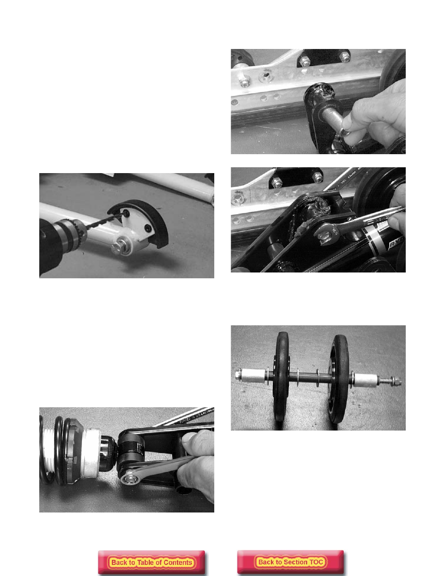
4. Inspect the two rear track guide bumpers. If worn,

drill out the rivets securing the bumpers to the arm
and replace with new bumpers.

AG486D

5. Inspect the shock absorber for any signs of oil

leakage especially at the point where the shock
shaft enters the shock body.

6. Inspect the shock absorber eyelet welds (at each

end) for any cracks, signs of separation, or for
unthreading.

7. Inspect the shock absorber for damage.

INSTALLING

1. Secure the shock eyelet to the front shock

mounting bracket. Tighten to 3.2 kg-m (23 ft-lb).

AG691D

2. Secure the front shock mounting bracket and axle

assembly to the rear shock pivot.

AG690D

AG689D

3. Slide the front idler wheel axle through the slide

rail; then install a spacer, large washer, idler
wheel, large washer, rear shock pivot, large
washer, idler wheel, large washer, and a spacer.

AG688D

4. Secure the front inner idler wheel assembly with a

cap screw, flat washer, lock washer, and a lock
nut. Tighten to 3.2 kg-m (23 ft-lb).

5. Position the front arm with spacers, an axle tube,

and serrated axles to the mounting brackets.
Secure with the cap screw and lock nut. Tighten to
4.2 kg-m  (30 ft-lb).

9-41

9

AG685D

6. Position the upper shock eyelet and serrated axle

in the front arm. Secure with a cap screw and lock
nut. Tighten to 3.2 kg-m (23 ft-lb).

AG582D

„

NOTE: Do not over-tighten the shock absorber

cap screw as the shock eyelet must be free to
pivot.

7. Secure the limiter straps with cap screws, washers,

and lock nuts. Tighten to 1.1 kg-m (8 ft-lb).

AG632D

Rear Shock Absorber 

and Shock Links

„

NOTE: The skid frame must be removed for this

procedure (see Removing Skid Frame in this sub-
section).

DISASSEMBLING

1. Using the Rear Suspension Spring Tool (p/n 0144-

311), remove the spring from the adjusting cam.

AG624DA

2. Remove the cap screw securing the lower shock

eyelet and shock links. Account for shock sleeves,
axle links, and a lock nut.

AG692D

„

NOTE: Lay components out in order as they are

removed.

3. Remove the cap screw and lock nut securing the

shock absorber at the upper eyelet and remove the
shock absorber. Account for a sleeve and bush-
ings.

! WARNING

Care must be taken when removing the spring from
the adjusting cam or damage or injury could result.

9-42

AG634D

4. Mark the hole that the upper shock links are

mounted in for assembly purposes; then remove
the cap screw and lock nut securing the shock
links to the upper arm bracket. Account for all
mounting hardware.

CLEANING AND INSPECTING

„

NOTE: Whenever a part is worn excessively,

cracked, or damaged in any way, replacement is
necessary.

1. Clean shock pivot and idler wheel axle in part-

cleaning solvent. Dry with compressed air.

2. Clean the idler wheel bearings with a clean cloth.

3. Closely inspect the idler wheel axle for wear,

bends, or damaged threads at either end.

4. Inspect the idler wheels for signs of cracking,

wear, or outer rubber separation from plastic
wheel.

5. Rotate the idler wheel bearings (by hand) and

inspect for any signs of binding or roughness.

6. If a bearing must be replaced, use this procedure.

A. Remove the wheel insert (if applicable) and the

snap ring.

B. Using a hydraulic press, press the bearing out

the inside of the wheel.

C. Press the new bearing (on its outer race) into

the idler wheel.

AG538D

D. Install the snap ring making sure the “sharp

side” is directed away from the bearing.

AG539D

E. Install the insert (if applicable).

7. Inspect the shock absorber for any signs of oil

leakage especially at the point where the shock
shaft enters the shock body.

8. Inspect the rubber shock bushings located in the

shock absorber eyelets for cracks or deterioration.

9. Inspect the shock absorber eyelet welds (at each

end) for any cracks or signs of separation.

10. Inspect the welds securing the eyelets of the shock

links for cracks or signs of separation. Either weld
the eyelet or replace the shock link.

11. Inspect the axle surfaces for any signs of corro-

sion. If corrosion is found, lightly buff the surface
of the axle with #400 wet-or-dry sandpaper; then
apply a light coat of grease.

! WARNING

Always wear an approved pair of safety glasses
when using compressed air.

! CAUTION

Do not remove the bearing unless it is absolutely
necessary. The bearing will be damaged during
removal.

9-43

9

ASSEMBLING

1. Secure the shock eyelet to the idler arm with

bushings, sleeve, lock nut, and a cap screw.
Tighten to 3.2 kg-m (23 ft-lb).

AG634D

2. Secure the rear shock links and the lower shock

absorber eyelet to the shock pivot bracket by plac-
ing the bushings and shock sleeve into the shock
eyelet; then install the axle links into the rear
shock links. Secure the assembly by installing a
cap screw and thin flat washer through the shock
link assembly, thick flat washer, shock pivot
bracket and shock eyelet assembly, thick flat
washer, shock link assembly, and a thin flat
washer. Secure the assembly with a lock nut.
Tighten to 3.2 kg-m (23 ft-lb).

AG692D

3. Position the shock links in the appropriate holes of

the idler arm brackets (see Chassis and Skid Frame
Mounting Locations in this section). Place a
spacer between the center of the brackets; then
place a flat washer on the cap screw. Insert the
axle links into the upper shock link eyelets; then
insert the cap screw with washer through the eye-
lets. Secure with a cap screw, washer, and lock
nut. Tighten to 3.2 kg-m (23 ft-lb).

Slide Rails

„

NOTE: The skid frame must be removed for this

procedure (see Removing Skid Frame in this sub-
section).

REMOVING

„

NOTE: When it is necessary to replace one or

both slide rails, it is recommended that one slide
rail be removed at a time. The remaining slide rail
will then hold the crossbraces, axles, and brackets
in their correct assembly order. Always mark the
mounting hole locations during disassembly to
speed up the assembly process and to prevent any
damage. This method is much quicker than to
completely disassemble the entire skid frame. To
replace either rail, use the following procedure.

1. Remove the end cap from the slide rail. Account

for a cap screw, lock nut, and two flat washers.

AG506D

2. Remove the machine screw and lock nut securing

the wear strip to the front of the slide rail.

AG509D

3. Using a pipe wrench and starting from either end,

hook the edge of the wear strip with the pipe
wrench jaw and twist the wear strip off the slide
rail. Move the pipe wrench 7.5 cm (3 in.) and
again twist the wear strip off the rail. Repeat this
procedure until the wear strip is free of the rail.


Content   ..  129  130  131  132   ..