Snowmobile Arctic Cat (2004 year). Manual - part 113


  Index      Snowmobiles / ATV     Snowmobile Arctic Cat - service manual 2004 year


Search            


Content   ..  111  112  113  114   ..


Snowmobile Arctic Cat (2004 year). Manual - part 113


8-52

AF058

15. Install the skid frame (see Section 9).

16. On standard models, remove the hold-down strap

securing the air-intake silencer; then place the
silencer into position making sure the boot is
properly positioned on the carburetors/throttle
body.

17. On standard models, secure the silencer to the

steering support with the two screws.

18. Apply a light coat of grease or Loctite Anti-Seize

Thread Compound (p/n 0678-146) to the driven
shaft; then install the driven shaft alignment
washers (as required) and key. Install the driven
pulley, stub shaft, alignment washers (as
required), washer, and cap screw. Tighten the cap
screw (coated with blue Loctite #243) to 2.6-
3.3 kg-m (19-24 ft-lb).

„ NOTE: Make sure keyways match when install-
ing the driven pulley. Arrange washers to allow the
least amount of float on the driven shaft. A maxi-
mum of 1.5 mm (0.060 in.) float is allowable.

AF057

19. Check the alignment of the drive clutch/driven

pulley (see Drive Clutch/Driven Pulley in this
section).

20. Tip the snowmobile onto the PTO-side using

cardboard to prevent scratching the belly pan; then
install the washers, rollers, and spring. Secure with
two washers and cotter pins.
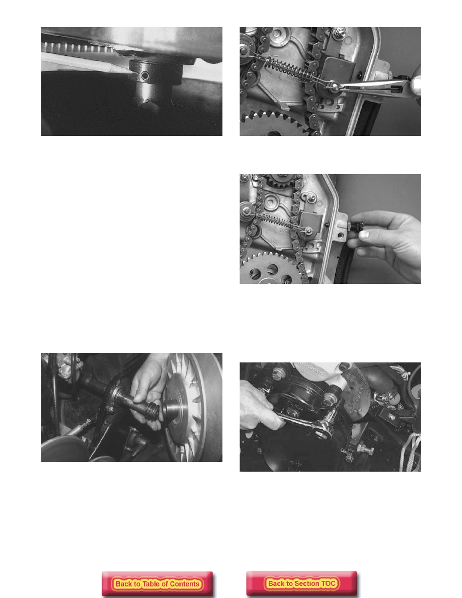
AF113D

21. Tighten the mechanical chain tensioner finger-

tight; then lock the jam nut against the chain case.

AF347D

22. Place the front roller cage and roller into position

and secure with the flex lock nut.

23. Check the position of the chain-case cover O-ring

seal; then place the chain-case cover into position
and secure with six cap screws and lock washers.
Tighten to 1.7-2.1 kg-m (12-15 ft-lb).

AF111D

24. Install the drain plug and tighten to 4.8 kg-m

(35 ft-lb); then pour 236 ml (8 fl oz) of Arctic Cat
Transmission Lube (p/n 0636-817) into the chain
case.

25. Install the drive belt and check drive belt

deflection (see Drive Clutch/Driven Pulley in this
section). Secure the belt guard.

8-53

8

Replacing Driven Shaft 

PTO-End Bearing          

(AWS VI Models)

REMOVING DRIVEN SHAFT

To remove the driven shaft, use the following
procedure:

1. Remove the driven pulley (see Driven Pulley in

this section).

FC135

2. Remove the two torx-head screws on the backside

pan near the left-side hood latch.

3. Drain the lubricant from the chain case.

4. Remove the six cap screws from the chain case

cover; then remove the cover.

FC137

5. Release chain tension; then remove the two lock

nuts and spring washers securing the top and
bottom sprockets. Account for and note the
orientation of the spring washers.

FC138

FC139

6. Remove the sprockets and chain.

7. Remove the four torx-head screws at the front left

side. Account for two lock nuts and cup washers.

FC136

„ NOTE: It may be necessary to use a magnet to
aid in retrieving the hardware.

8. Remove the three bearing retainer nuts from the

PTO-side plate brace; then remove the machine
screws securing the PTO-side plate brace and
remove the brace.

8-54

FC140

9. Remove the two large-head rivets below the left-

side air-out vent on the left-side belly pan.

FC141

10. Using a rubber mallet (or suitable substitute), tap

the driven shaft from the chain case side until free.

FC142

11. Pull down on the side pan by the left-side hood

latch; then slide the driven shaft out the PTO-side
of the chassis.

FC143

REPLACING BEARING

„  NOTE: Do not remove the brake disc stop collar
from the shaft. The stop collar is not a service part.
If damaged, the driven shaft must be replaced.

1. Using a suitable bearing press fixture, press the

bearing and spacer off the shaft.

FC144

2. Apply green Loctite #609 to the inner race of the

new bearing; then slide the bearing onto the shaft
(raised side of bearing directed to the PTO-end)
until it contacts the raised portion of the shaft.

FC146

„  NOTE: It is critical that the raised side of the
bearing is facing the PTO-end of the shaft.

8-55

8

3. Slide the spacer onto the shaft until it contacts the

bearing; then using a suitable bearing press
fixture, press the bearing and spacer onto the shaft
until the spacer is 10.4 cm (4.1 in.) in from the end
of the shaft.

FC145

FC147

INSTALLING DRIVEN SHAFT

1. Pull down on the side pan by the left-side hood

latch; then slide the driven shaft into the chassis
and into the chain case.

FC143

2. Place the PTO-side plate brace into position; then

install the three bearing retaining nuts on the PTO-
side plate brace. Tighten nuts securely.

FC140

3. Secure the brace with the machine screws.

FC136

4. Place the sprockets with chain into the chain case.

5. Secure the top sprocket with a lock nut (threads

coated with green Loctite #609) and spring
washer. Tighten to 4.8-5.5 kg-m (35-40 ft-lb).
Tighten the bottom sprocket lock nut with spring
washer to 4.8-5.5 kg-m (35-40 ft-lb).

! CAUTION

Do not press the bearing and spacer beyond the
given specification. Damage may occur to the
bearing, spacer, and shaft.


Content   ..  111  112  113  114   ..