Snowmobile Arctic Cat (2004 year). Manual - part 87


  Index      Snowmobiles / ATV     Snowmobile Arctic Cat - service manual 2004 year


Search            


Content   ..  85  86  87  88   ..


Snowmobile Arctic Cat (2004 year). Manual - part 87


7-12

INSTALLING

0737-346

1. Place the drag link in a vise; then secure the tie rod

to the drag link with cap screws, washers, and
lock nuts (threads coated with green Loctite #609).
Tighten to 2.8 kg-m (20 ft-lb).

2. Slide the drag link in from the side of the snowmo-

bile from which the steering boot was removed;
then carefully slide the boot over the tie rod end.

„

NOTE: Applying soapy water to the steering

boot will aid in sliding the boot over the tie rod
end.

3. Secure the drag link to the steering and idler arms

with cap screws (coated with green Loctite #609),
washers, bearing axles, and lock nuts. Tighten to
4.2 kg-m (30 ft-lb).

AL092

4. Secure the steering tie rod to the steering arm with

a cap screw (coated with green Loctite #609),
washer, and a lock nut. Tighten to 4.2 kg-m (30 ft-
lb).

5. Place the steering boot into position on the front

end (bulk head). Secure with self-tapping screws.

6. Install the tie rods (threaded area coated with

green Loctite #609) on the spindle arms as noted
during removing. Secure with O-rings, washers,
and lock nuts. Tighten to 4.2 kg-m (30 ft-lb).

AL108

AL655D

„

NOTE: Check all drag link and ball joint fasten-

ers to ensure they are tight. Turn the handlebars
full-left and full-right several times to ensure free
movement.

7. Install and secure the expansion chamber (if

removed).

8. Check and adjust ski alignment (see appropriate

Ski Alignment in this section).

Front Tie Rods           

(AWS V)

REMOVING AND DISASSEMBLING

1. Remove the lock nut securing the tie rod to the

spindle. Account for a washer and O-ring.
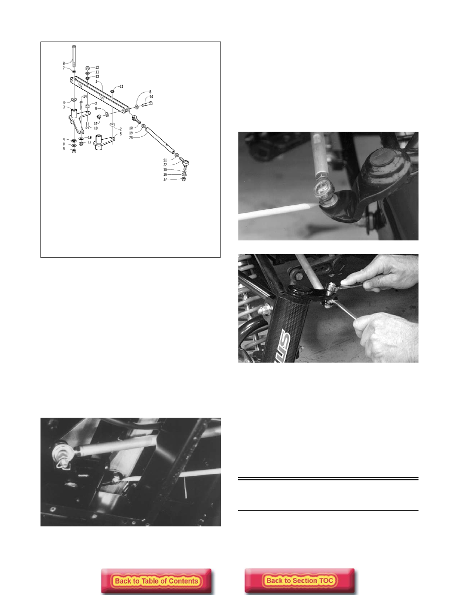
KEY

1. Drag Link
2. Bearing
3. Steering Arm
4. Insert
5. Steering Arm
6. Cap Screw
7. Washer
8. Washer

9. Lock Nut

10. Cap Screw
11. Washer
12. Lock Nut
13. Axle
14. Cap Screw
15. O-Ring
16. Washer

17. Lock Nut
18. Ball Joint 

(Right)

19. Hex Nut (Right)
20. Tie Rod Tube
21. Hex Nut (Left)
22. Ball Joint (Left)

7-13

7

„

NOTE: Note that the tie rod is installed on the

bottom side of the spindle arm for installing pur-
poses.

AL655D

2. Remove the self-tapping screws or rivets securing

the steering boot and retainer to the front end.

3. Turn the handlebar in the appropriate direction;

then remove the cap screw and lock nut securing
the steering arm to the drag link. Account for
washers.

4. Loosen the jam nut securing each ball joint to the

tie rod; then remove the ball joints from the tie
rod. Slide the rod from the steering boot. Remove
the jam nuts from the ball joints.

CLEANING AND INSPECTING

„

NOTE: Whenever a part is worn excessively,

cracked, or damaged in any way, replacement is
necessary.

1. Inspect the ball joints and tie rods for damaged

threads or wear.

2. Inspect the ball joints and tie rods for cracks or

unusual bends.

3. Wash the ball joints in parts-cleaning solvent. Dry

with compressed air. Inspect the ball joint pivot
area for wear. Apply a low-temperature grease to
the ball joints.

ASSEMBLING AND INSTALLING

1. Slide the tie rod through the steering boot and

retainer; then install the jam nuts on the ball joints
and thread the ball joints onto the tie rod.

„

NOTE: Each jam nut and ball joint is either a

right-hand or left-hand thread; therefore, each can
only be installed on one end of the tie rod. The
right-hand thread is the inside ball joint and jam
nut.

2. Secure the tie rod to the ball joint on the forked

end of the drag link with a cap screw, washers, and
lock nut. Tighten to 2.8 kg-m (20 ft-lb).

3. Secure the steering arm to the drag link with a cap

screw, lock nut, and washers. Tighten to 4.2 kg-m
(30 ft-lb).

4. Position an O-ring and washer on the ball joint

assembly (threads coated with green Loctite
#609). Install the ball joint on the spindle arm as
noted in removing; then secure with a lock nut.
Tighten to 4.2 kg-m (30 ft-lb).

AL655D

5. Place the steering boot and retainer into position

and secure with self-tapping screws or rivets.

6. Adjust ski alignment (see appropriate Ski Align-

ment in this section).

7. Apply blue Loctite #242 to the jam nut threaded

area and tighten the jam nuts against the tie rod to
1.7-2.1 kg-m (12-15 ft-lb).

Front Tie Rods           

(AWS VI)

REMOVING

1. Remove the lock nut securing the steering tie rod

to the upper arm of the steering shaft. Account for
the washer.

„

NOTE: Note that the tie rod is installed on the top

side of the upper arm for installing purposes.

! WARNING

Always wear safety glasses when using com-
pressed air.

! WARNING

Neglecting to lock the jam nuts against the tie rod
may cause loss of snowmobile control and possible
personal injury.

7-14

FC206

2. From the right-side, remove the Allen-head cap

screw (A) securing the two tie rod ends to the
lower arm of the steering shaft. 

FC207A

3. Remove the Allen-head cap screw securing the tie

rod to the right-side spindle arm.

4. From the left-side, remove the Allen-head cap

screw (B) securing the two tie rod ends to the
lower arm of the idler shaft. 

FC207B

5. Remove the Allen-head cap screw securing the tie

rod end to the left-side steering arm.

FC209

CLEANING AND INSPECTING

„

NOTE: Whenever a part is worn excessively,

cracked, or damaged in any way, replacement is
necessary.

1. Inspect the ball joints and tie rods for damaged

threads or wear.

2. Inspect the ball joints and tie rods for cracks or

unusual bends.

3. Wash the ball joints in parts-cleaning solvent. Dry

with compressed air. Inspect the ball joint pivot
area for wear. Apply a low-temperature grease to
the ball joints.

INSTALLING

0737-862

! WARNING

Always wear safety glasses when using com-
pressed air.

KEY

1. Steering Shaft
2. Thrust Washer
3. Thrust Washer
4. Lower Shaft 

Arm 

5. Snap Ring

6. Cap Screw
7. Idler Shaft
8. Ball Joint
9. Cap Screw

10. Tie Rod Tube
11. Hex Nut
12. Hex Nut

13. Ball Joint
14. Cap Screw
15. Ball Joint
16. Tie Rod Tube
17. Ball Joint
18. Plug

7-15

7

1. Place the two tie rod ends into position on the

lower arm of the idler shaft. Secure with the Allen-
head cap screw (B) coated with green Loctite
#609. Tighten to 5.5 kg-m (40 ft-lb).

FC207B

2. Place the tie rod into position on the left-side

steering arm. Secure with the Allen-head cap
screw coated with green Loctite #609. Tighten to
5.5 kg-m (40 ft-lb).

FC209

3. Place the two tie rod ends into position on the

lower arm of the steering shaft. Secure with the
Allen-head cap screw (A) coated with green
Loctite #609. Tighten to 5.5 kg-m (40 ft-lb).

FC207A

4. Place the tie rod into position on the right-side

spindle arm. Secure with the Allen-head cap screw
coated with green Loctite #609. Tighten to 5.5 kg-
m (40 ft-lb).

5. Place the steering tie rod into position on the upper

arm of the steering shaft. Secure with the washer
and lock nut (threads coated with green Loctite
#609). Tighten lock nut to 4.2 kg-m (30 ft-lb).

FC206

Spindle


(AWS V)

REMOVING

1. Position the front of the snowmobile up on a safety

stand.

2. Remove the ski.

3. Remove the lock nut and cap screw securing the

shock absorber to the spindle. Account for all
mounting hardware.

AL156D

4. Remove the lock nut securing the tie-rod ball joint

to the spindle (account for the washer and the O-
ring); then remove the ball joint from the spindle.

„

NOTE: Note that the tie rod is installed on the

bottom side of the spindle arm for installing pur-
poses.


Content   ..  85  86  87  88   ..