Snowmobile Arctic Cat (2004 year). Manual - part 63
5-19
5
To check battery condition, use a digital volt/ohmme-
ter set on DC volt scale. Test between the adjustment
tool black and red jacks. Insert the red lead of the digi-
tal voltmeter into the red jack of the adjustment tool
and the black lead of the digital voltmeter into the
black jack of the adjustment tool. If voltage is found
below 4.9 volts, replace the battery.
1. Using TPS Adjustment Tool (p/n 0644-299),
connect its wiring harness to the TPS. Connect the
two digital voltmeter leads (red and black) using
the two pin jack adapters provided with the
adjustment tool to the white and black jacks of the
TPS adjustment tool.
2. Ensure that the throttle cable has the proper
amount of free-play.
3. With the throttle in the idle position, compare the
reading on the voltmeter to the chart. If the reading
is at the prescribed specification, proceed to step 6.
If the reading is not at the prescribed specification,
proceed to step 4.
4. Using TPS Screwdriver (p/n 0644-344), loosen the
two retaining screws securing the TPS to the
throttle body.
5. Adjust the TPS to obtain the correct idle position
reading; then tighten the two retaining screws
securely.
6. Depress the throttle lever slowly. The meter
reading should show a smooth rise all the way to
wide-open throttle. Repeat this step until it is
assured that there are no open areas or “peaks” in
the reading.
7. Disconnect the adjustment tool harness from the
TPS. Connect the snowmobile TPS harness to the
newly installed or adjusted TPS.
NOTE: Before installing the TPS harness con-
nector, apply dielectric grease to the connector
pins.
REPLACING TPS (Carb Models)
NOTE: On EFI models, the TPS is not a service
part. The throttle body w/sensor must be replaced.
1. Disconnect the throttle cable from the throttle
shaft.
2. Turn the idle adjustment screw counterclockwise
until it is not in contact with the throttle lever.
3. Disconnect the TPS wiring harness connector.
Using TPS Screwdriver (p/n 0644-344), remove
the two retaining screws securing the TPS to the
carburetor/throttle body.
4. Install the new TPS and secure with two retaining
screws, flat washers, and lock washers.
5. Adjust the TPS using the appropriate procedures
in this sub-section.
FAIL-SAFE IGNITION TIMING
Engines equipped with throttle position sensor have a
protective feature called “fail-safe” ignition timing
which prevents engine damage should the TPS fail. If
the TPS does fail, the engine will run normally at low
RPM but will run poorly at high RPM. This will allow
the operator to get the snowmobile to safety with little
or no engine damage.
NOTE: The engine will continue to operate this
way until the TPS is replaced.
Testing Electrical
Resistances
(EFI Models)
NOTE: Resistance tests of the engine electrical
components should be made using the Fluke Mul-
timeter only. Analog-style multitesters may not be
accurate enough to use in these critical tests.
Replace any component that does not have a test
value within specifications.
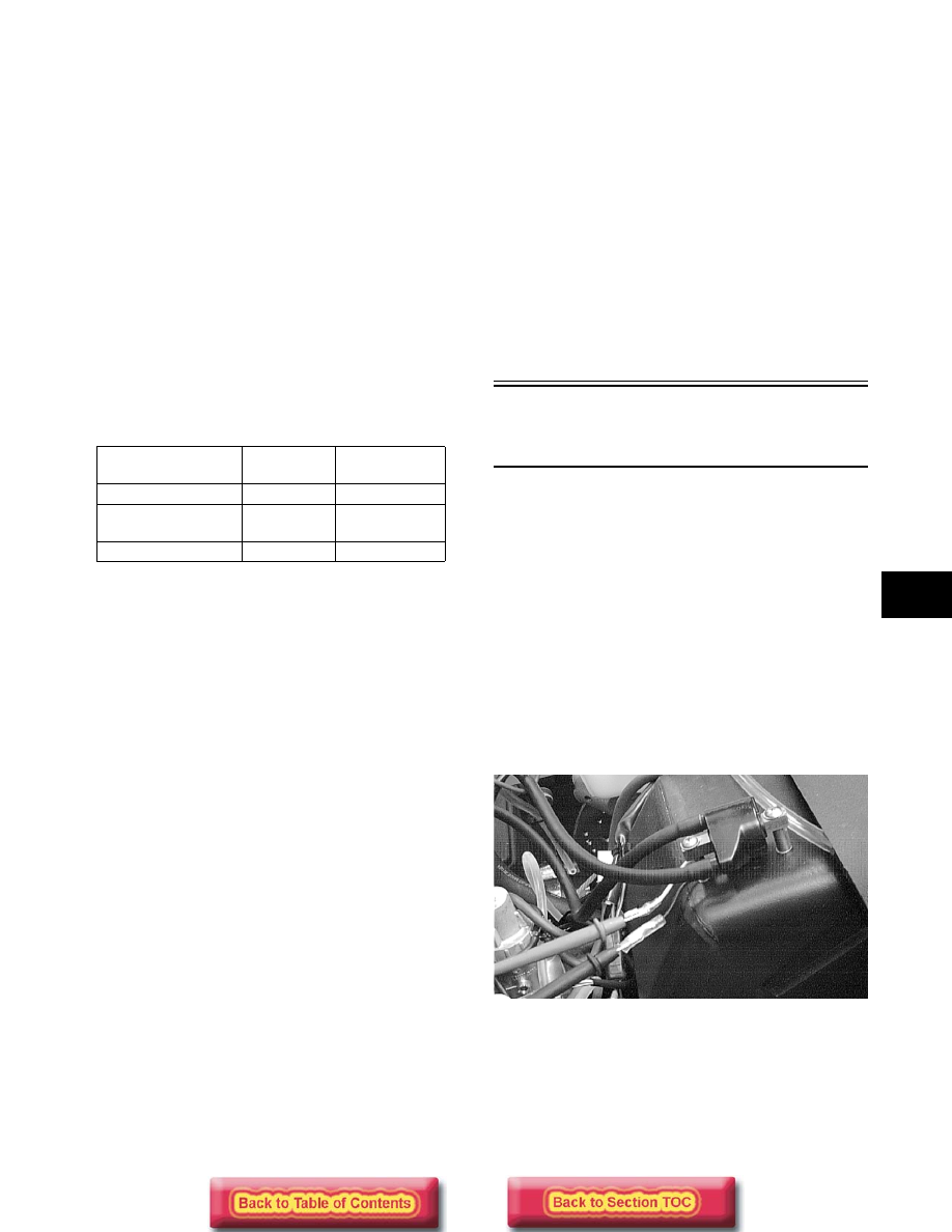
IGNITION COIL (Primary)
1. Disconnect the double wire plug from the ECU to
the ignition coil.
2. Set the selector in the X1 position.
3. Connect the red meter lead to the black/orange
lead; then connect the black meter lead to the
orange/black lead.
AK051D
4. Ignition coil primary resistance must be between
0.24-0.36 ohm.
IGNITION COIL (Secondary)
1. Remove the spark-plug caps from the high tension
wires.
2. Set the selector in the X1K position.
Engine
Idle
Position
Wide-Open
Position
600 cc (STD)
0.64V
3.575-3.937V
600/700 cc
(“Laydown”)
0.69-0.71V 3.575-3.937V
800/900
0.69-0.71V 3.575-3.937V