Snowmobile Arctic Cat (2004 year). Manual - part 52


  Index      Snowmobiles / ATV     Snowmobile Arctic Cat - service manual 2004 year


Search            


Content   ..  50  51  52  53   ..


Snowmobile Arctic Cat (2004 year). Manual - part 52


4-43

4

  2. Using TPS Adjustment Tool (p/n 0644-299), con-

nect its wiring harness to the TPS. Connect the
two Fluke meter leads (red and black) using the
two pin jack adapters provided with the adjust-
ment tool to the red and black jacks of the TPS
adjustment tool.

„

 NOTE: Before using the TPS adjustment tool,

verify its battery condition. The battery used in the
tool is a 9-volt battery. To check battery condition,
use a digital volt/ohmmeter set on DC volt scale.
Test between the adjustment tool black and red
jacks. Insert the red lead of the digital voltmeter
into the red jack of the adjustment tool and the
black lead of the digital voltmeter into the black
jack of the adjustment tool. If voltage is found
below 4.9 volts, replace the battery.

3. Set the multimeter selector to the DC scale; then

SLOWLY depress the throttle lever. The meter
reading should show a smooth rise all the way to
wide-open throttle. Repeat this step until it is
assured that there are no open areas or “peaks” in
the reading.

„

 NOTE: If a reading contains open areas or

peaks, the throttle position sensor may be faulty.
Refer to the proper Checking/Adjusting TPS proce-
dure in Section 5 - Digital 3-D Ignition in this man-
ual.

  4. Disconnect the adjustment tool harness from the

TPS. Connect the snowmobile TPS harness to the
TPS.

„

 NOTE: Before installing the TPS harness con-

nector, apply dielectric grease to the connector
pins.    

FUEL INJECTORS

AO139D

Testing Resistance/Voltage

1. Disconnect the fuel injector wiring harness.

2. Set the meter selector to the OHMS scale.

3. Test between the two injector terminals. Test

specification is 2.4-3.3 ohms.

AO144D

4. If not within specifications, replace the injector.
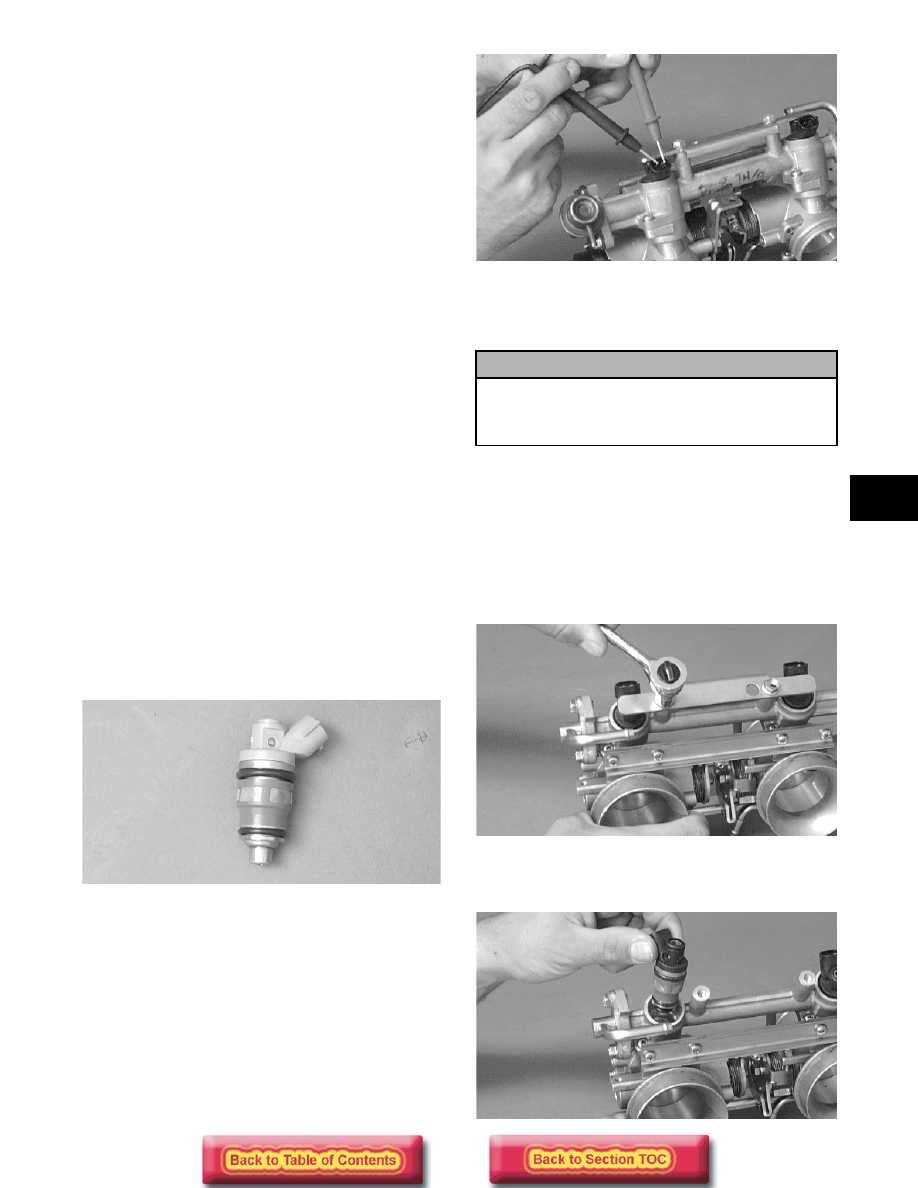
Removing

1. Loosen the clamp securing the fuel supply hose to

the fuel rail; then remove the hose from the fuel
rail.

2. Disconnect the wiring harness from each injector.

3. Remove the two screws securing the injector hold-

down plate to the throttle body assembly; then
remove the plate from the injectors.

AO145D

4. Remove the fuel injectors from the throttle body

assembly.

AO146D

! CAUTION

The fuel supply hose may be under pressure.
Place an absorbent towel around the connection
to absorb fuel; then remove the hose slowly to
release the pressure.

4-44

Installing

1. Apply a light coat of oil to all O-rings; then install

the upper and lower O-rings onto each injector.

2. Install the injectors into the throttle body

assembly.

3. Place the injector hold-down plate into position on

top of the injectors and secure with two screws.

4. Connect the fuel delivery hose to the fuel rail and

secure with a clamp.

„

NOTE: When securing the fuel delivery hose,

position the clamp as shown.

0729-325

5. Connect the wiring harness to the injectors making

sure the number 1 harness is connected to the
MAG-side injector.

IGNITION TIMING SENSOR

0729-627

„

NOTE: This sensor is located on the top of the

magneto case on some models. On other models
the sensor is located inside the magneto case next
to the flywheel, and on these models, the recoil
starter and the flywheel must be removed to
access the sensor.

Testing Resistance

1. Disconnect the two leads from the sensor to the

main wiring harness.

2. Set the meter selector to the OHMS scale.

3. Test between the green/white and brown leads

from the sensor. Test specification is 152-228
ohms.

AO147D

Removing

1. Open the rubber boot that protects the main wiring

harness connections; then disconnect the ignition
timing sensor from the ECU wiring harness.

2. Remove the two screws securing the sensor to the

magneto housing.

3. Remove the sensor.

Installing

1. Using two screws coated with blue Loctite #242,

secure the sensor to the magneto housing (inner
mounting hole).

2. Connect the sensor to the ECU wiring harness;

then close the rubber boot.

3. Secure loose wires with cable ties.

ELECTRIC FUEL PUMP

1. Remove the hardware securing the console to the

gas tank and frame; then move the console out of
the way.

2. Disconnect the fuel pump (white two-wire

connector on standard EFI models or black two-
wire connector on “Laydown” engine EFI models)
from the main wiring harness.

3. Connect the positive lead of a 12-volt power

supply to  the red wire and the negative lead of the
12-volt power supply to the black wire.

4. The pump should operate (it would be heard

running).

„

NOTE: If the fuel pump fails to operate, the pump

is defective and must be replaced.

4-45

4

FUEL PRESSURE REGULATOR 
(600 cc STD)

Removing

1. Loosen the clamp securing the fuel return hose to

the fuel regulator; then remove the hose.

2. Remove the two screws securing the fuel pressure

regulator to the fuel rail; then slowly remove the
regulator. Account for the O-ring.

AO149D

Testing Fuel Pressure Regulator

1. Using the Fuel Pressure Tester (p/n 0644-203),

connect the tester to the regulator fuel inlet.

AO053

„

NOTE: A short piece of 3/8 in. I.D. hose will be

needed to make the above connections.

2. Pressurize the regulator to 2.0-2.2 kg/cm² (28-31.3

psi). Turn the pressure tester shut off valve to the
OFF position. Observe the gauge for several
minutes and note if there is any loss of pressure. If
pressure begins to drop, the cause may be a
ruptured diaphragm, worn spring, or leaking
valve. If the regulator fails to build or maintain
pressure, replace the regulator.

„

NOTE: If there is a drop in pressure, check the

hose connections to ensure there are no leaks.

Installing

1. Position the O-ring on the fuel pressure regulator;

then place the regulator into position on the fuel
rail. Secure with two screws.

2. Connect the fuel return hose to the regulator; then

secure with a clamp.

0729-325

WATER TEMPERATURE SENSOR

Testing Resistance

„

NOTE: The water temperature sensor is very

sensitive to temperature change. Before the resis-
tance test is conducted, it is important to know the
coolant temperature. If the engine has been oper-
ated recently and the coolant is warm, the resis-
tance will measure lower than if the coolant was at
room temperature or colder. For accurate test
results, check the coolant temperature in the filler
neck using a thermometer.

1. Disconnect the water temperature sensor wiring

harness from the main harness.

2. Set the meter selector to the OHMS position and

test the resistance between the two leads from the
sensor.

3. Compare the resistance reading to the EFI

Component Voltage/Resistance Chart - Water
Temperature in this sub-section. If resistance is
not within the specification, replace the sensor.

„

NOTE: A water temperature sensor voltage test

can be made using the EFI Analyzer. Please refer
to the analyzer test procedures provided on the
following pages.

Removing

1. Drain the cooling system.

2. Remove the throttle body assembly.

3. Disconnect the wiring harness from the water

temperature sensor.

! CAUTION

Since the regulator may be under pressure,
remove it slowly to release the pressure. Place
an absorbent towel around the connection to
absorb fuel.

4-46

4. Remove the sensor from the water temperature

case.

Installing

1. Apply teflon tape to the threads of the water

temperature sensor; then install the sensor.

2. Connect the wiring harness to the sensor.

3. Install the throttle body assembly.

4. Fill the cooling system.

INTAKE AIR TEMPERATURE SENSOR

Testing Resistance

„

NOTE: It is very important to know the compo-

nent temperature before conducting this test.
Allow the engine to reach room temperature.

1. Disconnect the wiring harness from the intake air

temperature sensor.

AO135D

2. Set the meter selector in the OHMS position and

test the two leads located in the sensor connector.
Compare with the EFI Component Voltage/
Resistance Chart - Air Temperature in this sub-
section.

„

NOTE: The intake air temperature sensor

employs a thermistor, which is very sensitive to
temperature changes. Resistance will change as
temperature varies.

Removing

1. Disconnect the wiring harness from the intake air

temperature sensor.

2. Using a standard screwdriver, pry the sensor end

to end to remove it from the air-intake silencer.
Account for two push pins.

Installing

1. Place the sensor into position in the air-intake

silencer and secure with push pins.

2. Connect the wiring harness to the intake air

temperature sensor. Secure the sensor leads with
cable ties so they do not rub on any other
components.

EFI Analyzer

„

NOTE: Troubleshooting EFI engines with the

APV system should be done with the Arctic Cat
EFI Analyzer (p/n 0644-342). To update your exist-
ing EFI Analyzer, order Update Harness Kit (p/n
0644-341). For “Laydown” engine models, use EFI
Analyzer Update Kit (p/n 0637-243).

GENERAL INFORMATION

The EFI Analyzer (p/n 0644-342) makes it possible for
technicians to easily perform EFI system troubleshoot-
ing in a short period of time.

To use the analyzer on the batteryless EFI system, a
12-volt battery to power the analyzer is necessary. Fol-
low the instructions under Analyzer Setup for testing
the batteryless EFI system.

Analyzer Nomenclature

730-222A

1. LCD - Liquid Crystal Display.

2. Power-Light illuminates when the analyzer is

properly connected to the snowmobile EFI
analysis test plug.

3. On/Off Switches.

4. Menu Select (up/down) - Enables selection of a

test function quickly.

5. Test - Once the test function is selected, push the

button to complete the test. The button also
cancels the current test so the next test function
can be selected.

Analyzer Test Function 
(Batteryless System)

There is special information which can be retrieved
from the 2004 ECU such as total running time on
engine, running times by temperature, maximum RPM
by temperature, EPROM chip change check, number
of fuel changes by wire disconnect, and last fuel type
used. This information can only be retrieved with the
EFI analyzer. 


Content   ..  50  51  52  53   ..