Snowmobile Arctic Cat (2004 year). Manual - part 46
4-19
4
5. Secure the mixing body top by tightening the
screw and lock washer making sure the mixing
body top plate is properly positioned.
6. If applicable, connect the safety switch harness to
the main wiring harness.
7. Turn the gas tank shut-off valve to the OPEN
position.
8. Adjust the carburetors (see appropriate Adjusting
Carburetors in this sub-section).
Installing Carburetors
(Standard TM-Style)
1. Prior to installing the carburetors, the carburetor
throttle valves must be checked for
synchronization.
A. With the throttle in the idle position, select a
small drill bit that will just fit under the
cutaway of the fixed throttle valve.
B. Using the same drill bit, check the clearance
under the adjustable throttle valve cutaway. If
clearance is different from the first carburetor
checked, adjust the throttle valve by loosening
the lever ring locking screw; then using an
open-end wrench, rotate the synchronizing nut
in either direction until the clearance is the
same as the first carburetor checked.
0734-445
C. After synchronization has been attained, hold
the synchronizing nut with the open-end
wrench and tighten the lever ring locking
screw.
2. Place the carburetors (with float chamber vent
hoses) in the engine compartment and into the
carburetor boot; then tighten the clamps.
3. Connect the fuel supply hose to the fuel inlet T-
fitting.
4. Connect the throttle cable and choke cables.
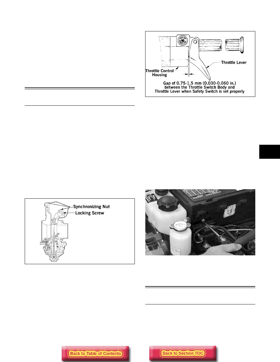
5. At this point, there must be free-play gap in the
throttle lever.
733-081C
NOTE: If throttle cable free-play is incorrect, the
throttle safety switch will be activated prematurely
and the engine will not start.
NOTE: If cable free-play must be corrected, uti-
lize the jam nuts on the throttle cable bracket until
no free-play is attained.
6. Place the air-intake silencer into position in the
engine compartment making sure the carburetors
are properly positioned in the boot and secure with
screws.
7. Place the ignition coil/fuel pump mounting plate
into position on the air-intake silencer and secure
with the machine screw and washer.
AN613D
8. Adjust the carburetors (see appropriate Adjusting
Carburetors in this sub-section).
Installing Carburetors
(“Laydown” Engine TM-Style)
1. Prior to installing the carburetors, the carburetor
throttle valves must be checked for
synchronization.