Snowmobile Arctic Cat (2004 year). Manual - part 31


  Index      Snowmobiles / ATV     Snowmobile Arctic Cat - service manual 2004 year


Search            


Content   ..  29  30  31  32   ..


Snowmobile Arctic Cat (2004 year). Manual - part 31


2-111

2

3. Connect all electrical wiring making sure all

wiring and coolant hoses are routed properly; then
place the engine into the mounting position.

„

NOTE: Use cable ties to secure the wiring har-

nesses as necessary.

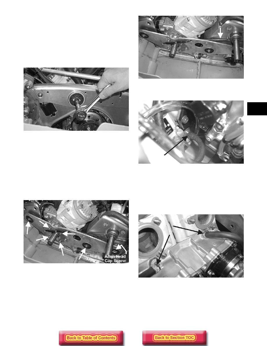
4. Install the cap screw securing the right-side engine

mounting bracket to the side plate. DO NOT
TIGHTEN AT THIS TIME.

FC011

5. Install the left-side engine mounting bracket with

the reinforcement plate securing the mounting
bracket to the engine; then secure the mounting
bracket to the front frame. Tighten bracket
hardware to 1-1.2 kg-m (7-9 ft-lb).

6. Tighten the four mounting bracket/reinforcement

plate to engine 8 mm cap screws to 2.5-2.8 kg-m
(18-20 ft-lb); then tighten the two lock nuts and
one Allen-head cap screw with lock nut to 2.5-2.8
kg-m (18-20 ft-lb). Tighten the right-side engine
cap screw and nut to 2.5-2.8 kg-m (18-20 ft-lb).

FC010A

7. Connect the oil-injection cable/control rod to the

oil-injection pump and secure; then route the oil-
supply hose through the left-side engine mounting
bracket, into the reinforcement plate, and to the
pump and secure with the clamp. Bleed the oil-
injection system (see Section 4).

FC008A

8. On carbureted models, connect the impulse hose

to the crankcase.

FC007A

9. Confirm that the two coolant hoses which run

beneath each exhaust port on the cylinders are
accessible to connect and that the fuel line and oil
pump linkage (EFI) or cable (carbureted) and
impulse lines are connected; then place the throttle
bodies/carburetors into position and secure with
the flange clamps. Synchronize the oil-injection
pump (see Section 4).

FC050A

2-112

FC051

10. Install the side-plate brace onto the chassis and

secure with the three cap nuts and four torx-head
screws.

FC009

11. Install the exhaust manifold noting that the gaskets

are directional (can go on only one way); then
install the four cap nuts and tighten to 1.8-2.2 kg-
m (13-16 ft-lb).

FC049

12. Fill the cooling system (see Liquid Cooling

System in Section 3).

13. Place the recoil starter with ground wire into

position and secure the starter with four cap
screws and lock washers. Tighten to 1 kg-m (7 ft-
lb).

FC052

„

NOTE: Steps 14-16 are for APV-equipped

engines only.

14. Slide the cable drums into the servomotor

actuator; then place the cable housings into
position in the servomotor. Secure the cable
housings with the cable retaining cover.

FC006A

FC006B

15. Place the servomotor cover into position; then

secure with two cap screws.

2-113

2

FC004

16. Check APV cable adjustment. See Arctic Power

Valve (APV) System in Section 3.

„

NOTE: Before installing the drive clutch, be sure

to wipe both the crankshaft taper and clutch
mounting taper clean using a clean towel.

„

NOTE: Before installing the drive clutch, it must

be locked in the compressed position.

17. Place the drive clutch into position on the

crankshaft and secure with the cap screw and lock
washer. Tighten to 6.9-7.6 lg-m (50-55 ft-lb).

FC002

18. Using Clutch Compressor (p/n 0644-420),

compress the drive clutch and remove the locking
clamp.

19. Install the driven pulley (with inner and outer O-

rings), key, stub shaft, and alignment washers.
Secure with a cap screw and washer. Tighten to
2.6-3.3 kg-m (19-24 ft-lb).

„

NOTE: Apply a coat of Anti-Seize Thread Com-

pound (p/n 0678-146) to the keyway end of the
driven shaft.

FC053

FC003

SC013D

20. Check drive clutch/driven pulley alignment (see

Section 8).

FC092

21. Install the drive belt. Check belt deflection. Secure

the belt guard.

! WARNING

Never attempt to start the engine without removing
the locking clamp from the drive clutch. Severe
damage and/or injury may occur.

2-114

22. Install the resonator and secure with three springs;

then place the expansion chamber and grafoil
gaskets into position and secure to the exhaust
manifold and resonator with the springs.

FC001

„

NOTE: When installing the three exhaust mani-

fold springs, the long hook protion of the spring
must be attached to the exhaust manifold or pre-
mature spring failure will result.

23. Start engine and verify ignition timing.

24. Test drive or run the snowmobile and recheck the

coolant level after 5-6 minutes. Tighten the drive
clutch cap screw to 7.6 kg-m (55 ft-lb).

! CAUTION

If the engine had a major overhaul or if any major
component was replaced, proper engine break-in
procedures must be followed. If the proper
engine break-in procedures are not followed,
sever engine damage may result.


Content   ..  29  30  31  32   ..