Snowmobile Arctic Cat (2004 year). Manual - part 19


  Index      Snowmobiles / ATV     Snowmobile Arctic Cat - service manual 2004 year


Search            


Content   ..  17  18  19  20   ..


Snowmobile Arctic Cat (2004 year). Manual - part 19


2-63

2

FC059

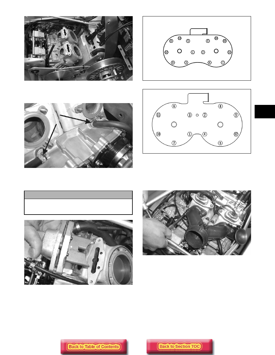
4. Connect the two coolant hoses on the cylinders

beneath the exhaust ports.

FC050A

5. Install the APV’s onto the cylinder and secure with

existing hardware.

FC056

6. Place the cylinder head into position on the

cylinders making sure the O-rings are properly
positioned; then on the 500 cc in two steps, tighten
the 6 mm cap screws to 0.9-1.3 kg-m (6.5-9.5 ft-
lb) and on all models in two steps, tighten the
8 mm cap screws to 2.1-3.1 kg-m (15-22.5 ft-lb)
using the appropriate pattern shown.

0738-204

0738-205

7. Install the coolant hose and breather hose onto the

cylinder head.

8. Install the exhaust manifold. Tighten existing

hardware to 1.8-2.2 kg-m (13-16 ft-lb).

FC049

9. Install the expansion chamber and resonator using

existing hardware. 

10. Install the side-plate brace and secure with

existing hardware.

11. Fill the cooling system with recommended coolant

(see Liquid Cooling System in Section 3). 

! CAUTION

The long side of the exhaust valve must be
facing toward the cylinder head or severe engine
damage may occur.

2-64

Cleaning and Inspecting 

Engine

„

NOTE: Whenever a part is worn excessively,

cracked, or damaged in any way, replacement is
necessary.

CYLINDER HEADS

1. Using a non-metallic carbon removal tool, remove

any carbon buildup from the combustion chambers
being careful not to nick, scrape, or damage the
combustion chambers or the sealing surfaces.

2. Inspect the spark-plug holes for any damaged

threads. Repair damaged threads using a heli-coil
insert.

3. Place the cylinder heads on a Surface Plate (p/n

0644-016) covered with #400 grit wet-or-dry
sandpaper. Using light pressure, move each
cylinder head in a figure eight motion. Inspect the
sealing surface for any indication of high spots. A
high spot can be noted by a bright metallic finish.
Correct any high spots before assembly by
continuing to move the cylinder head in a figure
eight motion until a uniform bright metallic finish
is attained.

AQ132D

CYLINDER HEAD (500/600/700 cc)

1. Using a non-metallic carbon removal tool, remove

any carbon buildup from the combustion chambers
being careful not to nick, scrape, or damage the
combustion chambers or the sealing surfaces.

2. Inspect the spark-plug holes for any damaged

threads. Repair damaged threads using a heli-coil
insert.

3. Inspect the cylinder head for flatness using a

straightedge and a feeler gauge. Acceptable
warpage must not exceed 0.05 mm (0.002 in.).

„

NOTE: If the warpage exceeds specification,

resurface the cylinder head using procedures
identified in step 6 in the Crankcase sub-section of
Cleaning and Inspecting Engine.

AN426D

CYLINDERS

1. Using a non-metallic carbon removal tool, remove

carbon buildup from the exhaust ports.

2. Wash the cylinders in parts-cleaning solvent.

3. Inspect the cylinders for pitting, scoring, scuffing,

and corrosion. If marks are found, repair the
surface with Ball Hone (p/n 0644-293) for the 600/
800 cc or (p/n 0644-294) for the 900 cc or with
#500 grit stones and honing oil.

FC037

„

NOTE: To produce the proper 60° crosshatch

pattern, use a low RPM drill (600 RPM) at the rate
of 30 strokes per minute. If honing oil is not avail-
able, use a lightweight, petroleum-based oil. Thor-
oughly clean the cylinders after honing using
detergent soap and hot water and dry with com-
pressed air; then immediately apply oil to the cyl-
inder bores. If a bore is severely damaged or
gouged, the cylinder will have to be replaced.

! CAUTION

Water or parts-cleaning solvent must be used in
conjunction with the wet-or-dry sandpaper or
damage to the sealing surface may result.

! CAUTION

Water or parts-cleaning solvent must be used in
conjunction with the wet-or-dry sandpaper or
damage to the sealing surface may result.

2-65

2

4. Place the head surface of each cylinder on the

surface plate covered with #400 grit wet-or-dry
sandpaper. Using light pressure, move each
cylinder in a figure eight motion. Inspect the
surface for any indication of high spots. A high
spot can be noted by a bright metallic finish.
Correct any high spots before assembly by
continuing to move the cylinder in a figure eight
motion until a uniform bright metallic finish is
attained.

PISTON ASSEMBLY

1. Using a non-metallic carbon removal tool, remove

the carbon buildup from the dome of each piston.

2. Take an old piston ring and snap it into two pieces;

then grind the end of the old ring to a 45° angle
and to a sharp edge. Using the sharpened ring as a
tool, clean carbon from the ring-grooves. Be sure
to position the ring with its tapered side up.

3. Inspect each piston for cracks in the piston pin and

skirt areas.

4. Inspect each piston for seizure marks or scuffing.

Repair with #400 grit wet-or-dry sandpaper and
water or honing oil.

AN135

„

NOTE: If scuffing or seizure marks are too deep

to correct with the sandpaper, it will be necessary
to replace the piston.

5. Inspect the perimeter of each piston for signs of

excessive “blowby.” Excessive “blowby” indicates
worn piston rings or an out-of-round cylinder.

CRANKCASE

1. Wash the crankcase halves in parts-cleaning

solvent.

„

NOTE: Before washing the crankcase halves,

make sure the four bearing dowel pins have been
removed and accounted for.

2. Inspect the crankcase halves for scoring, pitting,

scuffing, or any imperfections in the casting.

3. Inspect all threaded areas for damaged or stripped

threads.

4. Inspect the bearing areas for cracks or excessive

bearing movement. If evidence of excessive
bearing movement is noted, repair by peening the
bearing area in a pinking (sawtooth) pattern.

5. Inspect the bearing dowel pins for wear.

6. Inspect the sealing surfaces of the crankcase

halves for trueness by placing each crankcase half
on the surface plate covered with #400 grit wet-or-
dry sandpaper. Using light pressure, move each
half in a figure eight motion. Inspect the sealing
surfaces for any indication of high spots. A high
spot can be noted by a bright metallic finish.
Correct any high spots by continuing to move the
half in a figure eight motion until a uniform bright
metallic finish is attained.

„

NOTE: Care must be taken not to remove an

excessive amount of aluminum, or the crankcase
will have to be replaced. If excessive aluminum is
removed, too much pre-load will be exerted on the
crankshaft bearings when assembled.

AN060

! CAUTION

Water or parts-cleaning solvent must be used in
conjunction with the wet-or-dry sandpaper or
damage to the sealing surface may result.

! CAUTION

Improper cleaning of the ring-grooves by the use
of the wrong type of ring-groove cleaner will
result in severe damage to the piston.

! CAUTION

Water or parts-cleaning solvent must be used in
conjunction with the wet-or-dry sandpaper or
damage to the sealing surface may result.

2-66

INTAKE MANIFOLD
INSULATORS (Single Carburetor)/
ADAPTER PLATES (Twin Carburetors)

„

NOTE: For fan cooled models only.

1. Inspect for cracks, scoring, pitting, imperfections,

or warping.

2. Inspect the sealing surfaces for trueness by placing

each on the surface plate covered with #400 grit
wet-or-dry sandpaper. Using light pressure, move
both sides in a figure eight motion. Inspect the
sealing surface for any indication of high spots or
warping. Correct high spots by continuing to move
each side in a figure eight motion. Warped
components must be replaced.

„

NOTE: On the twin carburetor model in order to

inspect adapter plate trueness, it will be necessary
to remove the studs.

A932

CRANKSHAFT

1. Wash the crankshaft with bearings in parts-

cleaning solvent.

2. Inspect the bearings for wear, scoring, scuffing,

damage, or discoloration. Rotate the bearings.
Bearings must rotate freely and must not bind or
feel rough. If any abnormal condition is noted,
replace the bearing.

FC039

3. Inspect the connecting-rod bearings by rotating

them. The bearings must rotate freely and must not
bind or feel rough. If a connecting-rod bearing
must be replaced, the connecting rod and crank pin
must also be replaced.

FC040

4. Inspect the oil-injection pump drive gear for any

signs of worn or chipped teeth. If either condition
exists, replace the gear.

„

NOTE: Lubricate bearings thoroughly prior to

assembly.

REMOVING OUTER 
CRANKSHAFT BEARINGS

„

NOTE: Steps 1-3 are for removing the MAG-side

bearing.

1. Place a bearing support (block of wood, etc.)

beneath the MAG-side bearing.

! CAUTION

Water or parts-cleaning solvent must be used in
conjunction with the wet-or-dry sandpaper or
damage to the sealing surfaces may result.

! WARNING

Safety glasses must be worn when spreading bear-
ings.

! CAUTION

A bearing support must be positioned beneath
the bearing that is being removed to prevent
crankshaft damage.


Content   ..  17  18  19  20   ..