Snowmobile Arctic Cat (2004 year). Manual - part 13


  Index      Snowmobiles / ATV     Snowmobile Arctic Cat - service manual 2004 year


Search            


Content   ..  11  12  13  14   ..


Snowmobile Arctic Cat (2004 year). Manual - part 13


2-39

2

Disassembling Engine

(570 cc Models)

1.  Remove the exhaust manifold. Account for the

gaskets.

2.  Remove the nuts, lock washers, and washers

securing the intake flange assembly. Account for
the gaskets, insulators, and the heat deflector.

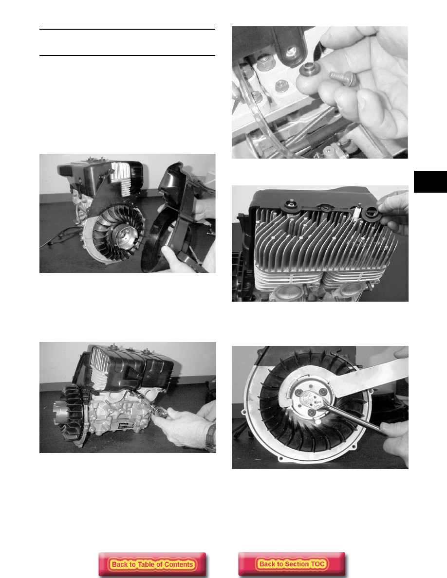
3.  Remove eight cap screws securing the main fan

shroud; then remove the shroud with the recoil
starter assembly.

MD0279

„

NOTE: Cap screws securing the front and rear

shrouds use special washers.

4. Remove the five cap screws securing the front

(exhaust-side) shroud to the cylinder head.
Account for the special washers.

MD0276

„

NOTE: Keep the special mounting hardware with

the shrouds for assembling purposes.

MD0065

5. Remove the spark plug grommets.

MD0060

6. Using Spanner Wrench (p/n 0144-007) to hold the

starter pulley, remove the cap screw securing the
flywheel to the crankshaft.

MD0282

7. Using Spanner Wrench (p/n 0144-007) to hold the

starter pulley, remove the three cap screws
securing the starter pulley and fan to the flywheel.

2-40

MD0000

8. Install Flywheel Puller Insert (p/n 0644-179) into

the end of the crankshaft. Using Flywheel Puller/
Spanner Wrench (p/n 0144-310) or suitable
substitute, remove the flywheel.

AN615

„

NOTE: To ensure the cleanliness of the flywheel

magnets, place the flywheel (with the magnets fac-
ing upward) on a clean bench.

9. Remove the six cap screws securing the rear

(intake-side) shroud; then remove the shroud.
Account for the special washers.

MD0277

MD0067

10. Remove the rubber insulator grommet from the

crankcase; then remove two Phillips-head cap
screws securing the ignition timing sensor and pull
the wires through the hole in the crankcase. 

MD0075

! CAUTION

To prevent damage to the crankshaft, install a
protective insert into the end of the crankshaft.
The puller must bottom on the insert and not on
the crankshaft. Also, do not thread puller bolts
more than five threads into the flywheel. Damage
to the stator coils may result.

2-41

2

MD0074

11.  Remove the three Allen-head cap screws securing

the stator and remove it along with the stator
wiring.

MD0072

MD0076

12. Remove the four Allen-head cap screws securing

the stator plate. Remove the stator plate.

MD0255

MD0078

13. Remove the four cap screws securing the seal

retainer plate on the PTO-side; then remove the
plate.

MD0081

14. Remove the spark plugs.

2-42

MD0083

15. Remove the eight cap screws, two nuts, and two

washers securing the cylinder head to the
cylinders; then remove the cylinder head. Discard
the cylinder head gasket.

MD0289

16. Remove the four 6 mm nuts and eight 10 mm nuts

securing the cylinders to the crankcase.

„

NOTE: Using a felt-tip marker, mark the cylinders

as to MAG-side and PTO-side for assembling.
Also, mark the pistons at this time.

MD0087

MD0086

17. Remove the cylinders making sure to support the

pistons so they are not damaged. Account for four
dowel pins.

MD0230

MD0096

18. Using an awl, remove the outside piston-pin

circlip and remove the piston pin using Piston Pin
Puller (p/n 0644-328) taking care not to drop the
piston-pin bearing washers into the crankcase.

! CAUTION

When removing a cylinder, make sure to support
the piston so it will not be damaged.


Content   ..  11  12  13  14   ..