Snowmobile Arctic Cat (2004 year). Manual - part 10


  Index      Snowmobiles / ATV     Snowmobile Arctic Cat - service manual 2004 year


Search            


Content   ..  8  9  10  11   ..


Snowmobile Arctic Cat (2004 year). Manual - part 10


2-27

2

AP118B

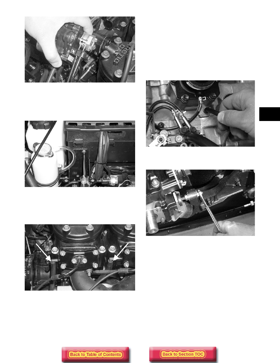
10. Remove the screw securing the servomotor

mounting plate to the air-intake silencer; then pull
the mounting plate forward and up to remove it
from the silencer. Lay the mounting plate aside out
of the way.

AP127

11. Lift the silencer cover and remove the CDI unit;

then lay the unit aside out of the way.

12. Remove the two APV drain hoses and route them

out of the way.

AP128A

13. If applicable, remove the machine screw and

washer securing the mounting plate (for the
ignition coil and fuel pump) to the air-intake
silencer.

14. Remove the screws securing the air-intake

silencer; then move the silencer forward and out of
the engine compartment.

15. Disconnect the oil-injection cable/control rod from

the oil-injection pump; then disconnect the oil-
supply hose from the pump and plug the hose to
prevent oil drainage.

16. Loosen the flange clamps securing the throttle

body/carburetor to the flange; then remove the
throttle body/carburetor. Place them to one side in
an upright position.

17. On carbureted models, disconnect the impulse

hose from the crankcase.

AN385D

18. Loosen the engine torque bumper and remove the

left rear engine nut and washer.

AN610D

19. Secure the hood with a tie-down strap; then

remove the hood cable.

20. Disconnect all electrical wires from the engine.

21. Remove the recoil starter from the engine. Leave it

in the engine compartment.

„

NOTE: If applicable, disconnect the solenoid-to-

starter motor cable from the starter motor.

22. Loosen the cap screws/lock nuts securing the

engine mounting brackets to the front end.

23. Remove the cap from the coolant drain hose and

route the hose into a suitable container. Remove
the filler cap; then once the coolant stops draining,
install the drain hose cap.

2-28

AP126

24. Loosen the clamp securing the supply hose to the

coolant tank and remove the hose. Loosen the
clamp securing the hose to the thermostat cap;
then remove the hose from the cap.

„

NOTE: Inspect the engine to ensure all wires,

hoses, and cables have been removed.

25. Lift the engine with mounting brackets out of the

engine compartment.

26. Remove the cap screws securing the engine

mounting brackets to the crankcase; then remove
the brackets.

27. Remove the exhaust manifold from the engine.

Account for nuts, washers, and gaskets.

28. Remove the clamp securing the coolant supply

hose to the water pump. Then remove the hose
from the pump.

Removing Engine

(550 cc Model)

1. Disconnect the battery cables making sure to

disconnect the negative cable first.

2. Turn the gas tank shut-off valve to the CLOSED

position.

3. Remove the cable tie and positive battery cable

from the starter motor.

4. Remove the springs securing the expansion

chamber to the exhaust manifold, front end, and
resonator. Remove the expansion chamber and
grafoil gasket.

5. Attach a long piece of fuel hose to the engine

coolant drain (located on the exhaust side of the
engine). Route the hose outside the engine
compartment and into a container. Open the drain
and remove the filler cap. Once the coolant stops
flowing, remove the hose and tighten the drain
valve.

AP058

6. Open the belt guard: then remove the drive belt.

„

NOTE: Remove the rubber plug from the belly

pan.

7. Using a ½-in. twelve-point socket, remove the bolt

and lock washer securing the drive clutch to the
crankshaft. Using the Clutch Puller (p/n 0644-207)
and an impact wrench or a breaker bar and the
Flywheel Pulley/Spanner Wrench (p/n 0144-310),
tighten the puller. If the drive clutch will not
release, sharply strike the head of the puller.
Repeat this step until the clutch releases. Remove
the drive clutch. If applicable, account for the two
sleeves.

8. Remove the cap screw and washer securing the

driven pulley; then slide the driven pulley off the
driven shaft. Account for a key and alignment
washers.

AF120D

„

NOTE: If the driven pulley is tight on the driven

shaft, pull the driven pulley off using the Driven
Pulley Puller (p/n 0744-023).

9. Loosen the flange clamp securing each carburetor

to its flange; then remove the carburetors. Position
the carburetors to one side in an upright position.

2-29

2

AJ172

10. Disconnect the impulse hose from the crankcase.

11. Remove the cable tie securing the engine and CDI

wiring harnesses to the engine; then disconnect the
main wiring harness from the engine and CDI
wiring harnesses.

12. Remove the spark plug caps and the cable tie

securing the temperature-gauge sender wire; then
disconnect the sender wire.

13. Remove the E-clip and washer securing the oil-

injection cable; then disconnect the oil-injection
cable from the pump. Disconnect the oil-supply
hose from the pump and plug the hose to prevent
oil drainage.

AN009

14. Loosen the clamp securing the supply hose to the

water pump housing; then remove the hose from
the water pump. Loosen the clamp securing the
hose to the thermostat cap; then remove the hose
from the cap.

15. Remove the four cap screws and lock washers

securing the recoil starter; then remove the starter
from the engine. Leave it in the engine
compartment.

„

NOTE: On the Pantera 550, account for the

ground wire.

16. Support the hood; then remove the hood cable

from the exhaust manifold.

17. Remove the mounting hardware securing the

engine to the front end.

AR321

18. Lift the engine with mounting brackets out of the

engine compartment.

19. Remove the engine mounting brackets.

Removing Engine 


(500/600/700 cc

Laydown

Engine Models)

1. Remove all springs securing the expansion

chamber and resonator; then remove these
components from the engine compartment.

FC001

2. Open the belt guard; then remove the drive belt.

3. Remove the plug from the belly pan. Using a ½-in.

12-point socket, remove the cap screw and lock
washer securing the drive clutch to the crankshaft.

! CAUTION

Do not use the starter motor shaft to lift the
engine. Damage may occur.

2-30

FC002A

4. Using Clutch Compressor (p/n 0644-420), lock the

drive clutch in the compressed position with the
locking clamp.

FC260

FC261

5. Using Clutch Puller (p/n 0644-207) and an impact

wrench or a breaker bar and Spanner Wrench (p/n
0644-136), tighten the puller. If the drive clutch
will not release, sharply strike the head of the
puller. Repeat this step until the clutch releases.
Remove the drive clutch. If applicable, account for
the two sleeves.

FC002

6. Remove the cap screw and washer securing the

driven pulley; then slide the driven pulley off the
driven shaft. Account for a key, stub shaft,
alignment washers, and an inner and outer O-ring.

FC003

„

 NOTE: If the driven pulley is tight on the driven

shaft, pull the driven pulley off using the Driven
Pulley Puller (p/n 0744-023).

7. Loosen the two cap screws securing the

servomotor and cover; then remove the cover.
Using a small screwdriver, pry off the cable
retaining cover.

FC004


Content   ..  8  9  10  11   ..