Snowmobile Arctic Cat (2002 year). Manual - part 112


  Index      Snowmobiles / ATV     Snowmobile Arctic Cat - service manual 2002 year


Search            


Content   ..  110  111  112  113   ..


Snowmobile Arctic Cat (2002 year). Manual - part 112


8-6

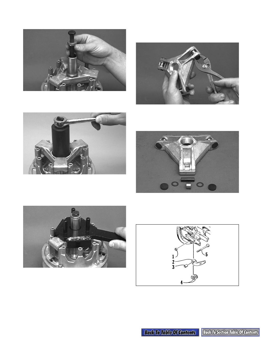
4. Secure the drive clutch to the holder using the

clutch bolt and lock washer.

AM064D

5. Using the Thin Wall Deep Socket (p/n 0644-138),

remove the spider retainer nut.

AM065D

6. Using a small torch, heat the threaded area of the

spider. Place the Spider Removal Tool (p/n 0644-

085) over the heated spider and break spider loose

by turning it counterclockwise.

AM067D

„ NOTE: Applying heat to the spider threaded area
will aid in clutch disassembly. The heat will loosen
the Loctite used during assembly.

7. Remove the drive clutch from the clutch holder

using the clutch puller and the same procedure as

pulling the drive clutch from the crankshaft.

8. Remove the spider, spacer washers, and movable

sheave.

9. Using a pair of pliers, remove the six spider

buttons.

AM070D

10. Using a punch, push each pin from the roller.

Account for the roller washers (one on each side of

each roller).

AM071D

11. Remove the three cam arm pins and lock nuts

securing the cam arms to the movable sheave; then

remove each cam arm and account for the

bushings and the washers.

733-452B

KEY

1. Lock Nut
2. Cam Arm
3. Bushing
4. Washer
5. Pin

8-7

8

CLEANING AND INSPECTING

„ NOTE: Whenever a part is worn excessively,
cracked, or damaged in any way, replacement is
necessary.

1. Using parts-cleaning solvent, wash grease, dirt,

and foreign matter off all components; dry with

compressed air.

2. Remove any drive belt dust accumulation from the

stationary sheave, movable sheave, and bushings

using parts-cleaning solvent only.

3. Inspect stationary sheave, movable sheave, spider,

and cover for cracks or imperfections in the

casting.

4. Inspect the cam arm pins for wear or bends.

5. Inspect the bushing in the cover for wear, damage,

or cracks. Measure the inside diameter of the

bushing and the outside diameter of the stationary

sheave hub. The difference (clearance) must be

less than 0.20 mm (0.008 in.). If cover bushing is

not within specifications, replace the cover.

AM078D

AM077D

6. Inspect the bushing in the movable sheave for

wear, damage, or cracks. Measure the inside

diameter of the bushing and the outside diameter

of the stationary sheave hub. The difference

(clearance) must be less than 0.20 mm (0.008 in.).

If movable sheave bushing is not within

specifications, replace the movable sheave.

AM023D

AM079D

7. Inspect the spring for proper compression rate

qualities.

8. Inspect the cam arms for any uneven wear pattern

or damage to the bushings.

9. Inspect all threaded areas for any cracked or

stripped threads.

10. Inspect rollers for damage or wear.

11. Inspect the roller bushings for damage or fraying.

12. Inspect the stationary sheave and shaft for damage

or wear.

! CAUTION

Do not use steel wool or a wire brush to clean
components having a bushing; damage to the
bushing will result.

P/N

Color

Rate 

@ 2 9/16 in.

Rate

@ 1 5/16 in.

0646-148

Red/Blue

53 lb

224 lb

0646-150

Silver

72 lb

188 lb

0646-149

Red

74 lb

228 lb

0646-147

Yellow/Green

114 lb

267 lb

0646-155

Purple

121 lb

240 lb

0646-229

Yellow/White

122 lb

285 lb

0646-248

Orange/White

143 lb

290 lb

8-8

ASSEMBLING

0736-321

1. Place a cam arm with bushing and washers into

position on the movable sheave; then secure with

the cam arm pin and lock nut. Carefully tighten the

lock nut until it contacts the cam arm pin shoulder;

then tighten an additional 1/8 turn. Repeat

procedure on the other two cam arms making sure

the head of each pin is positioned toward the

direction of drive clutch rotation.

„ NOTE: The drive clutch rotates counterclock-
wise.

733-452B

2. Place a roller and washers (one on each side of the

roller) into position on the spider; then install the

pin. Repeat procedure on the other two rollers.

AM071D

3. Place the spider buttons into position; then tap into

place until firmly seated.

„ NOTE: If a spider button does not fit tightly, it
must be replaced.

4. Align the spider and movable sheave timing

marks.

5. Place the movable sheave, spacer washers, and

spider into position on the stationary sheave hub.

Make sure all threads are clean and free of oily

residue. Apply green Loctite #620 to the entire

threaded area of the shaft and thread the spider

onto the shaft. Tighten the spider using the spider

removal tool to 34.5 kg-m (250 ft-lb).

„ NOTE: Allow the Loctite to cure at room temper-
ature for 24 hours.

AM072A

6. Apply green Loctite #620 to the threads of the

stationary shaft above the spider. Install the spider

retainer nut and tighten to 11.8 kg-m (85 ft-lb).

! WARNING

Never reuse the lock nuts on the cam arm pins.

KEY

1. Stationary 

Sheave

2. Movable Sheave
3. Cover
4. Retainer Nut

5. Pin
6. Lock Nut
7. Cam Arm
8. Bushing
9. Washer

10. Spacer Washer
11. Spider Assy
12. Lock Washer
13. Machine Screw
14. Spring

KEY

1. Lock Nut
2. Cam Arm
3. Bushing
4. Washer
5. Pin

! CAUTION

Failure to align the spider and movable sheave
timing marks will cause drive clutch to be out of
balance resulting in clutch and crankshaft
damage.

8-9

8

AM066

„ NOTE: Grasp the movable sheave and lift it
upward; then release it. It must move freely and
not bind at any point.

7. Place the spring and cover into position making

sure the timing mark on the cover is properly

aligned; then compress the spring and install the

nine machine screws coated with blue Loctite

#242 and lock washers. Tighten evenly to

1.4 kg-m (10 ft-lb).

AM075

AM076

INSTALLING

1. Install any spacers as accounted for in removing;

then insert the clutch bolt with lock washer.

„ NOTE: Be sure to wipe the clutch taper and
crankshaft taper clean of any oil film or dirt before
installing the drive clutch.

2. Place the clutch into position on the crankshaft.

3. Using a 12-point 1/2-in. socket and the drive

clutch spanner wrench, tighten the clutch bolt to

6.9-7.6 kg-m (50-55 ft-lb).

AF477D

4. Check alignment between the drive clutch and

driven pulley (see Drive Clutch/Driven Pulley in

this section).

AF468D

5. Install the drive belt. Check drive belt deflection

(see Drive Clutch/Driven Pulley in this section).

Secure the belt guard and install the plug in the

belly pan.

! CAUTION

Care must be taken when installing the cover not
to damage the bushing.

! CAUTION

When installing the drive clutch, do not tighten
the clutch bolt with any kind of impact tool.
Tighten clutch bolt using a hand torque wrench
only. Failure to do so could result in stationary
sheave damage.

! WARNING

Never operate the engine without the belt guard
secured.


Content   ..  110  111  112  113   ..