Snowmobile Arctic Cat (2002 year). Manual - part 59


  Index      Snowmobiles / ATV     Snowmobile Arctic Cat - service manual 2002 year


Search            


Content   ..  57  58  59  60   ..


Snowmobile Arctic Cat (2002 year). Manual - part 59


4-29

4

0734-445

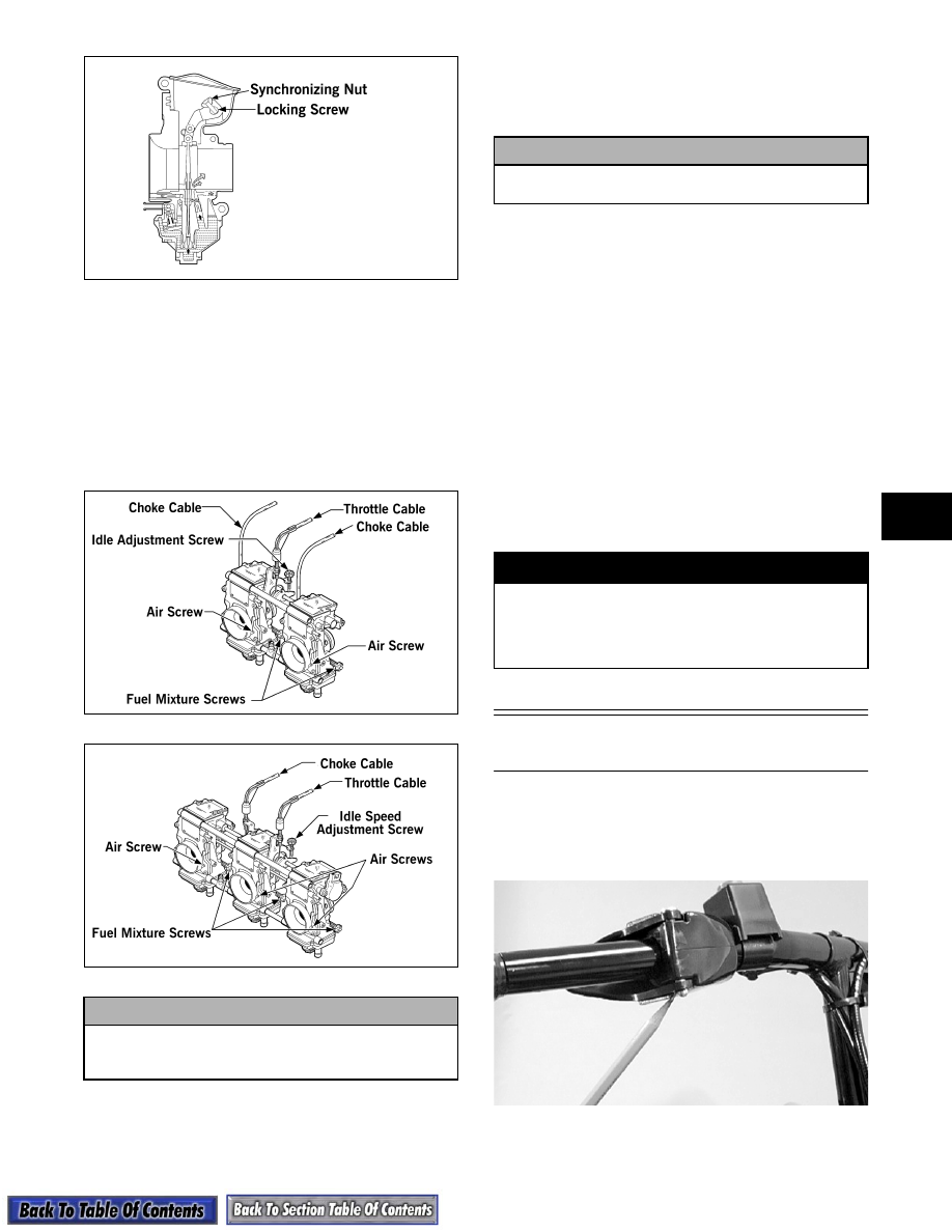
6. After synchronization has been attained, hold the

synchronizing nut with the open-end wrench and

tighten the lever ring locking screw.

7. Install the resonator and cover/tool tray assembly.

ADJUSTING FUEL MIXTURE SCREWS

1. While counting the rotations, carefully rotate the

fuel mixture screws clockwise until lightly seated.

0735-774

0735-857

2. Rotate each fuel mixture screw counterclockwise

the same number of turns as noted in step 1 for an

initial setting.

ADJUSTING AIR SCREWS

1. While counting the rotations, carefully rotate the

air screws clockwise until lightly seated.

2. Rotate the air screws counterclockwise the exact

number of rotations ± 1/4 turn from the seated

position as an initial setting.

ADJUSTING ENGINE IDLE SPEED

„

NOTE: Make engine idle adjustment only after

the engine has reached running temperature.
Since the idle speed screw has not been adjusted,
apply slight throttle pressure to keep the engine
running. Allow engine to warm up for 2-3 minutes.

1. After the engine has been allowed to warm up for

2-3 minutes, fine-tune the idle speed screw until

the tachometer reads 1500 RPM.

2. Test the throttle control lever by compressing and

releasing it several times. The lever must return to

the idle position quickly and completely.

Throttle Cable

(BV-Style)

REMOVING AND INSPECTING

1. Remove the C-clip securing the lever pin in the

throttle lever; then remove the pin and the lever.

A979

2. Disconnect the throttle cable from the lever; then

slide the cable out of the lever.

! CAUTION

Do not force a fuel mixture screw when rotating it
clockwise; damage to the mixture screw taper
may result.

! CAUTION

Do not force an air screw when rotating it
clockwise; damage to the air screw will result.

! WARNING

DO NOT operate the snowmobile when any compo-
nent in the throttle system is damaged, frayed,
kinked, worn, or improperly adjusted. If the snow-
mobile is operated when the throttle system is not
functioning properly, personal injury could result.

4-30

A980

3. Remove the C-clip securing the cable in the

throttle control; then remove the cable from the

throttle control.

A981

A982

4. Remove the handlebar pad and cut the cable tie

securing the throttle cable to the steering post.

„

NOTE: Note the location of the cable tie for

assembly.

5. Loosen the throttle cable binding screw; then

loosen the throttle cable jam nuts and remove the

throttle cable.

0735-459

6. Inspect the throttle cable for damage or fraying.

INSTALLING

1. Route the cable through the slot in the throttle

control and insert the cable into the throttle

control. Secure the cable with a C-clip.

A981

2. Seat the cable drum into the throttle lever recess;

then secure the throttle lever to the throttle control

with a pin and C-clip.

A980

4-31

4

A979

3. Place the throttle cable into the throttle cable

bracket and secure with jam nuts.

4. Slide the tip of the throttle cable into the throttle

actuator and tighten the binding screw.

5. Secure the throttle cable to the steering post with a

cable tie; then install the handlebar pad.

„

NOTE: At this point, spray the binding screw

drum (located on the carburetor throttle arm) with
WD-40 or an equivalent lubricant.

ADJUSTING

1. The correct throttle cable adjustment is when (with

the engine OFF) the carburetor throttle is

completely open (against its limit) while the

throttle control lever lightly contacts the hand grip.

The throttle arm on the carburetor should also

contact the throttle stop screw when the throttle

control is released. Adjust by using the following

procedure.

2. Loosen the throttle cable wire binding screw.

0735-459

3. Pull all slack from the throttle cable wire and exert

slight tension on the wire.

4. Tighten the throttle cable wire binding screw.

„

NOTE: The speed control screw is designed to

reduce the maximum speed of the snowmobile.

Throttle Cable

(VM-Style)

„

NOTE: Determine which type of cable is being

replaced and remove and install accordingly.

REMOVING

734-533A

736-742A

1. Loosen the throttle cable adjuster jam nuts.

2. Remove the mixing body tops.

3. Remove the throttle cables from the piston valves.

4. Remove the throttle cables from the mixing body

tops.

5. Remove the handlebar pad and console.

6. Remove the cable ties securing the throttle cable.

7. Remove the throttle cable end from the throttle

lever.

! WARNING

DO NOT operate the snowmobile when any compo-
nent in the throttle system is damaged, frayed,
kinked, worn, or improperly adjusted.

KEY

1. Retaining Ring
2. Throttle Cable
3. Cable Tie
4. E-Ring
5. Washer
6. Nut

KEY

1. Retaining Clip
2. Throttle Cable
3. E-Ring
4. Washer
5. Cable Tie
6. Jam Nut

4-32

8. Using Throttle Cable Removal Tool (p/n 1639-

963), push down on the throttle cable retaining

clip; then remove the cable from the throttle

switch assembly.

„

NOTE: On twin carburetor models, it may be nec-

essary to remove the PTO-side carburetor.

9. Remove the E-ring securing the oil-injection cable

to the control arm. Account for a washer.

10. Loosen the jam nut securing the adjustment cable;

then remove the cable from the oil-injection pump.

INSTALLING

1. Route the throttle cable from the throttle switch

assembly to the carburetors and oil-injection

pump; avoid any sharp bends or moving parts.

2. Install the oil-injection adjustment cable on the

oil-injection pump; secure with the jam nuts.

3. Install the oil-injection cable on the control arm;

secure with a washer and E-ring.

„

NOTE: Install the PTO-side carburetor if removed.

4. Install the throttle cable into the throttle switch

assembly making sure it snaps into place.

5. Install the throttle cable end on the throttle lever.

6. Secure the throttle cable to the steering post with

cable ties.

7. Install the handlebar pad and console.

8. Attach the throttle cable to each throttle valve. The

valve must seat in the groove of the throttle cable

end; then thread the throttle cable into each mixing

body top.

9. Install each piston valve and mixing body top on

the carburetor(s). Tighten securely.

10. Adjust the carburetor(s) (see appropriate

Adjusting Carburetors in this sub-section).

11. Synchronize the oil-injection pump (see Related

Items sub-section).

Throttle Cable

(TM-Style)

735-869A

REMOVING

1. Loosen the throttle cable adjuster jam nut at the

bracket.

2. Remove the throttle cable from the pulley on the

throttle lever shaft.

3. Remove the handlebar pad and console.

4. Remove the throttle cable from the throttle lever.

5. Using Throttle Cable Removal Tool (p/n 1639-

963), push down on the throttle cable retaining

clip; then remove the cable from the throttle

switch assembly.

6. Open the belt guard; then remove the drive belt.

7. Remove the oil-injection cable from the control

arm.

„

NOTE: Some models are equipped with “control

rod” actuated oil pump. The control rod simply
snaps off and on at the control arm.

8. Loosen the jam nut securing the adjustment cable;

then remove the cable from the oil-injection pump.

INSTALLING

1. Install the oil-injection adjustment cable on the

oil-injection pump; secure with the jam nuts.

2. Install the oil-injection cable on the control arm.

3. Route the throttle cable from the carburetor to the

throttle switch assembly making sure it snaps into

place.

! CAUTION

Compress the throttle control lever to ensure
free movement. If the throttle cable sticks or
binds, correct the problem before starting the
engine.

KEY

1. Retaining Clip
2. Throttle Cable
3. E-Ring
4. Washer
5. Cable Tie
6. Jam Nut


Content   ..  57  58  59  60   ..