Snowmobile Arctic Cat (2002 year). Manual - part 28


  Index      Snowmobiles / ATV     Snowmobile Arctic Cat - service manual 2002 year


Search            


Content   ..  26  27  28  29   ..


Snowmobile Arctic Cat (2002 year). Manual - part 28


2-95

2

AN074

6. Set the top half of the crankcase upside down on

the work bench with a 4 in. block of wood under

each end.

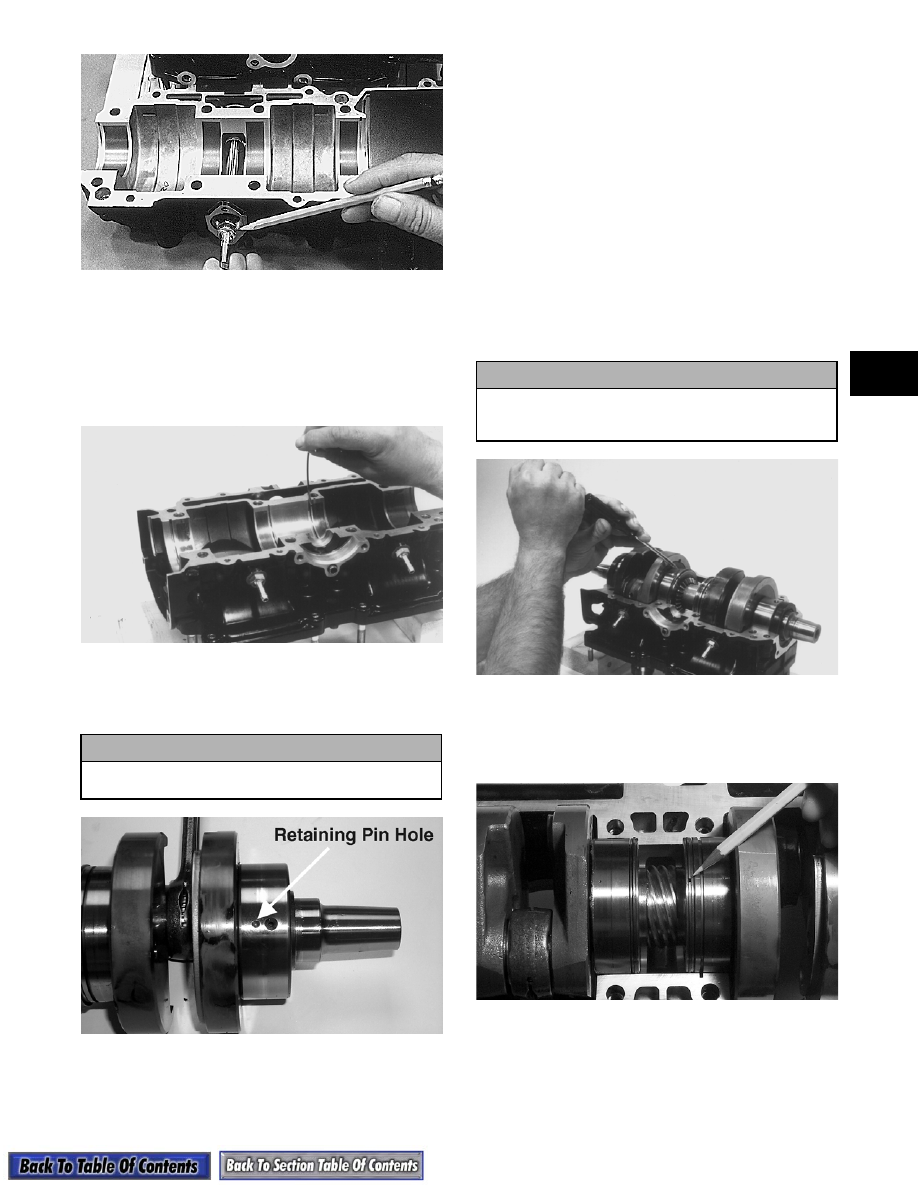
7. Install the C-ring in the upper crankcase half.

Install the four bearing retaining pins in the

crankcase bearing areas.

AJ095

8. Using Arctic Cat 50:1 Injection Oil, lubricate the

crankshaft bearings and slide them onto the

crankshaft.

AP150B

9. Lubricate the inner lips of the crankshaft oil seals

with grease; then slide the seals onto the

crankshaft making sure the spring side of each seal

faces the center of the crankcase.

„

NOTE: There is a MAG-side seal and a PTO-side

seal.

10. Apply Arctic Cat 50:1 Injection Oil to all of the

crankshaft bearings; then install the crankshaft

into the upper crankcase half. Be sure the retaining

pin hole in each bearing is positioned over its

respective dowel pin in the crankcase.

„

NOTE: Check all bearings by trying to rotate

them to make sure they are being held in position
by the retaining pin. Each bearing must drop onto
the retaining pin.

AJ097

11. Rotate the crankshaft center seal rings so the end

gaps of the two large rings are 180° apart, one end

gap being positioned downward and the other

upward; then seat the crankshaft.

AP151

12. Apply a thin coat of High-Temp Sealant (p/n

0636-069) to the lower crankcase sealing surface.

! CAUTION

The retaining pin holes on both bearings must be
positioned toward the center of the crankshaft.

! CAUTION

If the bearings are not properly seated during
assembly, the crankcase halves will not seal
tightly and severe engine damage will result.

2-96

AQ127

13. Assemble the crankcase halves.

14. Install the crankcase cap screws securing the

crankcase halves making sure the proper-sized cap

screws (on carbureted models) are in the proper

holes. Tighten in three steps the 10 mm cap screws

to 4.8-5.4 kg-m (35-39 ft-lb), the 8 mm cap screws

to 1.8-2.8 kg-m (13-20 ft-lb), and the 6 mm cap

screws to 0.9-1.3 kg-m (6.5-9.5 ft-lb) using the

pattern shown.

AJ101

736-280A

„

NOTE: On EFI models after assembling the

crankcase halves, install the magneto case .
Tighten to 1.8-2.2 kg-m (13-16 ft-lb).

15. Install the oil-injection pump retainer O-ring and

retainer.

AN088D

16. Install the O-ring and the oil-injection pump

making sure the pump shaft slot and pump driven

gear shaft align. Secure with two screws (coated

with blue Loctite #242) and washers. Tighten the

two screws to 1-1.4 kg-m (7-10 ft-lb).

AP143

17. Place the lower check valve assembly into position

and secure with the gaskets and the union bolt.

18. Position the rubber seal retainer and seal into the

back side of the water pump impeller.

19. Using both thumbs, press the seal into position

making sure its marked side is positioned towards

the rubber seal cup; then apply a thin coat of

grease to the seal outer surface.

! CAUTION

Check to make sure the two crankcase half
dowel pins are in position at opposite corners of
the lower case half.

! CAUTION

Be sure the oil-injection pump/water pump
driveshaft is properly aligned with the slot of the
oil-injection pump. The pump will be damaged if
these two components are not aligned.

2-97

2

20. Place the impeller into position and secure with a

cap screw and washer. Be sure the rubber side of

the washer is directed toward the impeller. Apply

blue Loctite #242 to the threads of the cap screw

and tighten to 0.8-1.2 kg-m (6-9 ft-lb).

21. Place the end plate into position on the crankcase;

then apply blue Loctite #242 to the four cap

screws and tighten securely.

AP142

22. Install the piston rings on each piston so the letter

on the top or inclined surface of each ring faces the

dome of the piston.

726-306A

23. Apply oil to the connecting-rod small end

bearings; then install the small-end bearings and

thrust washers.

AQ059

24. Place each piston over the connecting rod so the

arrow on each piston will point toward the exhaust

port and secure with a piston pin; then install the

new circlips so the open end is directed either

down or up.

AJ110

25. Apply a thin coat of Copper Coat Gasket Sealant

(p/n 0636-092) to both sides of each cylinder-base

gasket if the gaskets are being reused. If using new

gaskets, it isn't necessary to apply copper coat.

Install the gasket with the raised portion of the

gasket positioned upward.

AJ111

! CAUTION

The rubber side of the washer, which secures the
impeller, must be positioned toward the impeller.
If installed incorrectly, a coolant leak will result.

! CAUTION

Incorrect installation of the piston rings will
result in engine damage.

! CAUTION

Make sure circlips are firmly seated and the open
end is directed either down or up before
continuing with assembly.

2-98

26. Rotate each piston ring until the ring ends are

properly positioned on either side of the ring

keeper; then apply oil to the piston assemblies and

cylinder bores.

726-306B

27. In turn on each cylinder, place a piston holder (or

suitable substitute) beneath the piston skirt and

square the piston in respect to the crankcase; then

using a ring compressor or the fingers, compress

the rings and slide the cylinder over the piston.

Remove the piston holder and seat the cylinder

firmly onto the crankcase.

AP138

28. Secure each cylinder with four flange cap screws

and four nuts with flat and lock washers. Using a

crisscross pattern, tighten the nuts to 4.6-6.8 kg-m

(33-49 ft-lb) and the cap screws to 4.8-7.2 kg-m

(35-52 ft-lb).

29. Place the O-rings into position on the top of each

cylinder.

AJ118

„

NOTE: If reusing O-rings and they are slightly

stretched, shrink the O-rings by cooling them (in a
refrigerator for example) for a short period of time.

30. Check sealing surface to make sure the surface is

clean; then set the cylinder heads in position.

31. Apply a thin coat of High-Temp Sealant (p/n

0636-069) to the two thermostat manifold gaskets.

Place the gaskets and housing into position and

secure with four cap screws and washers. Tighten

the four cap screws in a crisscross pattern to 0.9-

1.3 kg-m (6.5-9.5 ft-lb).

„

NOTE: The thermostat manifold cap screws

must be tightened before tightening the head cap
screws. This will allow the gasket surfaces of the
head to align with the housing and prevent any
coolant leakage.

32. Tighten the head cap screws in three steps to 2.4-

3.2 kg-m (17-23 ft-lb) using the pattern shown;

then install the spark plugs and tighten to 2.5-2.8

kg-m (18-20 ft-lb).

0728-138

33. If removed in turn for each cylinder, install the

gasket, reed valve assembly, and carburetor flange

to the crankcase; then secure with six cap screws.

Tighten to 0.8-1.2 kg-m (6-9 ft-lb).

AN213

34. Test the engine for air leaks (see Section 3).

35. Place the thermostat with gasket and cap into

position. Secure with three cap screws. Tighten to

0.9-1.3 kg-m (6.5-9.5 ft-lb).


Content   ..  26  27  28  29   ..