Snowmobile Yamaha Phazer PZ50W, PZ50GTW, PZ50FXW, PZ50MW, PZ50VTW, PZ50MPW. Manual - part 60
5-77
ENG
13. Apply:
• Sealant
(onto the crankcase mating surfaces)
NOTE:
Do not allow any sealant to come into contact with
the oil gallery or crankshaft journal bearings. Do not
apply sealant to within 2 ~ 3 mm (0.08 ~ 0.12 in) of
the crankshaft journal bearings.
14. Install:
• Dowel pins
Yamaha bond No. 1215:
90890-85505
(Three Bond No.1215
®
)
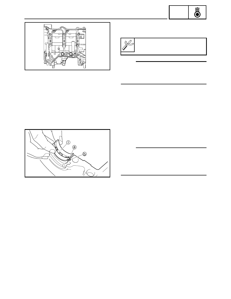
15. Install:
• Crankshaft journal bearings 1
(into the lower crankcase)
NOTE:
• Align the projections
a on the crankshaft journal
lower bearings with the notches
b in the crank-
case.
• Install each crankshaft journal lower bearing in its
original place.
16. Install:
• Lower crankcase
(onto the upper crankcase)