Snowmobile Yamaha Phazer PZ50W, PZ50GTW, PZ50FXW, PZ50MW, PZ50VTW, PZ50MPW. Manual - part 46
5-21
ENG
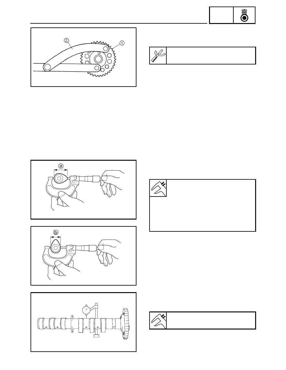
6. Remove:
• Intake camshaft sprocket 1
(Use the special tool 2)
Rotor holding tool:
90890-01235, YU-01235
INSPECTION
1. Inspect:
• Camshaft lobes
Blue discoloration/pitting/scratches
→
Replace the camshaft.
2. Measure:
• Camshaft lobe dimensions
a and b
Out of specification
→ Replace the camshaft.
Camshaft dimensions:
Intake:
<Limit>:
a 30.350 mm (1.1949 in)
b 22.510 mm (0.8862 in)
Exhaust:
<Limit>:
a 30.600 mm (1.2047 in)
b 22.493 mm (0.8856 in)
3. Measure:
• Camshaft runout
Out of specification
→ Replace.
Camshaft runout:
0.03 mm (0.0012 in)