Snowmobile Yamaha FX10X, FX10RTX, FX10RTRX, FX10RTRAX, FX10MTX, FX10MTRX, FX10MTRAX. Manual - part 67
6-12
COOL
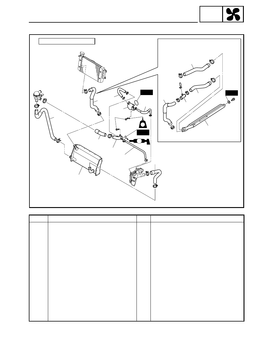
OIL COOLER AND HEAT EXCHANGER
Order
Job name/Part name
Q’ty
Remarks
Oil cooler and heat exchanger removal
Remove the parts in the order listed below.
Coolant
Drain.
Refer to “COOLING SYSTEM” in CHAPTER
2.
Engine assembly
Refer to “ENGINE ASSEMBLY” in CHAPTER
5.
1
Water pump outlet hose
1
2
Oil cooler outlet hose
1
3
Oil cooler
1
4
Water pump breather hose
1
5
Thermostat inlet hose
1
6
Cylinder head water jacket
1
7
Thermostat outlet hose
1
8
Radiator outlet hose
1
9
Water pump inlet hose
1
10
Heat exchanger
1
FX10MT/FX10MTR/FX10MTRA
LT
New
New
8
2
1
7
4
9
5
6
3
10
È
(4)
10 Nm (1.0 m
•
kg, 7.2 ft
•
lb)
È:
LS
8
11
13
12
14
New