Snowmobile Yamaha FX10X, FX10RTX, FX10RTRX, FX10RTRAX, FX10MTX, FX10MTRX, FX10MTRAX. Manual - part 52
5-28
ENG
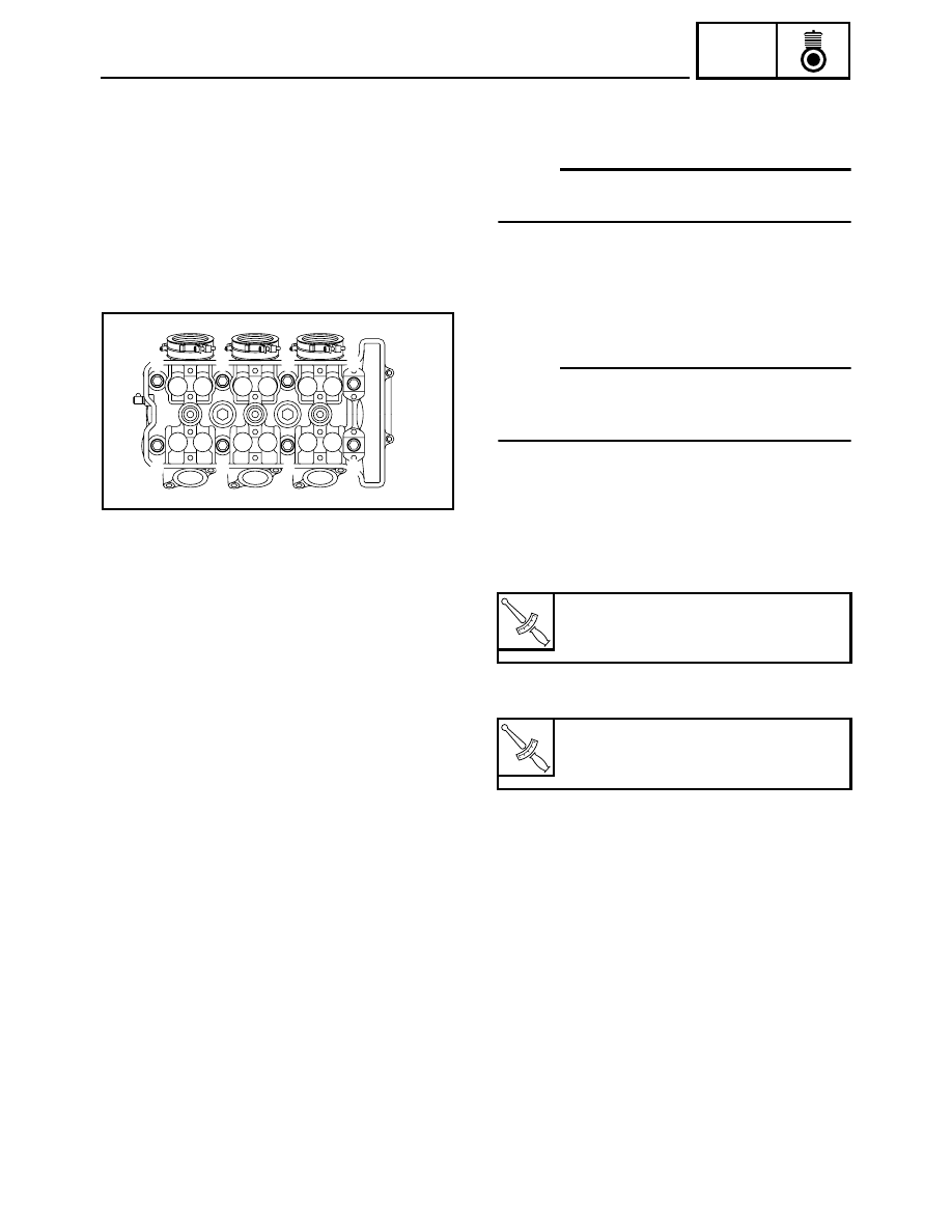
INSTALLATION
1. Install:
• Cylinder head
NOTE:
Pass the timing chain through the timing chain cav-
ity.
2. Tighten:
• Cylinder head bolts (M10)
NOTE:
The tightening procedure of the cylinder head bolts
is angle controlled, therefore tighten the bolts using
the following procedure.
Tightening steps:
• Lubricate the cylinder head bolts and washers
with engine oil.
• Install the washers and cylinder head bolts.
• Tighten the cylinder head bolts in the proper
tightening sequence as shown.
• Loosen and retighten the cylinder head bolts in
the proper tightening sequence as shown.
T
R
.
.
Cylinder head bolt (M10):
1st:
25 Nm (2.5 m · kg, 18 ft · lb)
T
R
.
.
Cylinder head bolt (M10):
2nd:
25 Nm (2.5 m · kg, 18 ft · lb)
6
7
3
1
5
2
4
8