Snowmobile Yamaha FX10X, FX10RTX, FX10RTRX, FX10RTRAX, FX10MTX, FX10MTRX, FX10MTRAX. Manual - part 29
4-5
POWR
TR
PRIMARY SHEAVE AND DRIVE V-BELT
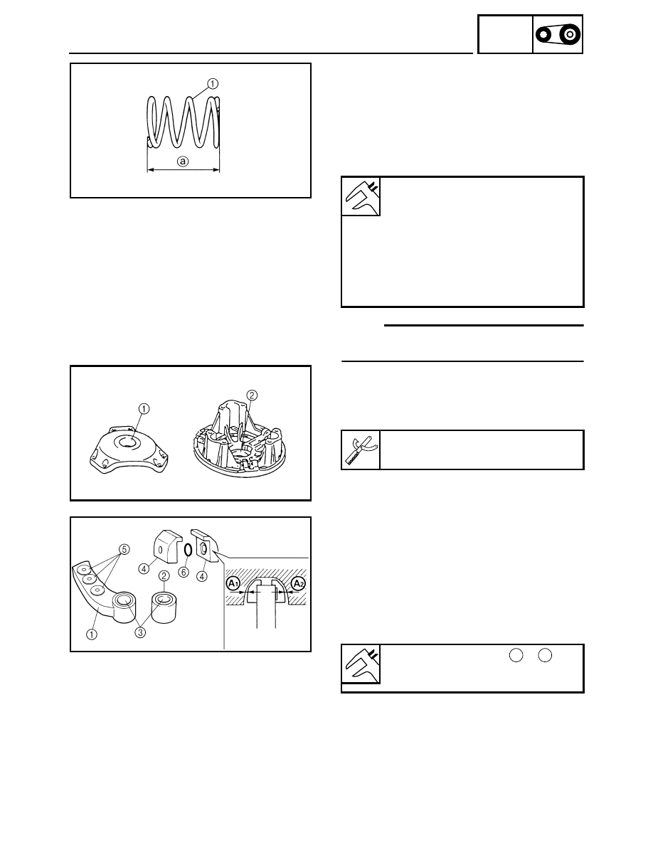
2. Inspect:
• Primary sheave spring 1
Cracks/damage
→ Replace.
3. Measure:
• Primary sheave spring (standard) free length
a
Out of specification
→ Replace the primary
sheave spring.
NOTE:
When changing the primary sheave springs, refer
to “GEAR SELECTION” in CHAPTER 2.
4. Inspect:
• Primary sheave cap bush 1
• Sliding sheave bush 2
Cracks/damage
→ Replace.
Primary sheave spring (standard)
free length:
FX10/FX10RT/FX10RTR/FX10RTRA
87.4 mm (3.44 in)
FX10MT “USA/Canada”/FX10MTR
“USA/Canada”
89.8 mm (3.54 in)
FX10MTR “Europe”/FX10MTRA
“Europe”
98.4 mm (3.87 in)
Clutch bushing press:
90890-01529, YS-42424
5. Inspect:
• Weight 1
• Roller 2
• Bushing 3
• Slider 4
• Rivet 5
• O-ring 6
• Collar
Wear/scratches/damage
→ Replace.
Slider inside clearance
+
:
Min. 0 mm (0 in)
Max. 0.3 mm (0.0118 in)
A
1
A
2