Snowmobile Yamaha FX10X, FX10RTX, FX10RTRX, FX10RTRAX, FX10MTX, FX10MTRX, FX10MTRAX. Manual - part 14
2-45
INSP
ADJ
ELECTRICAL
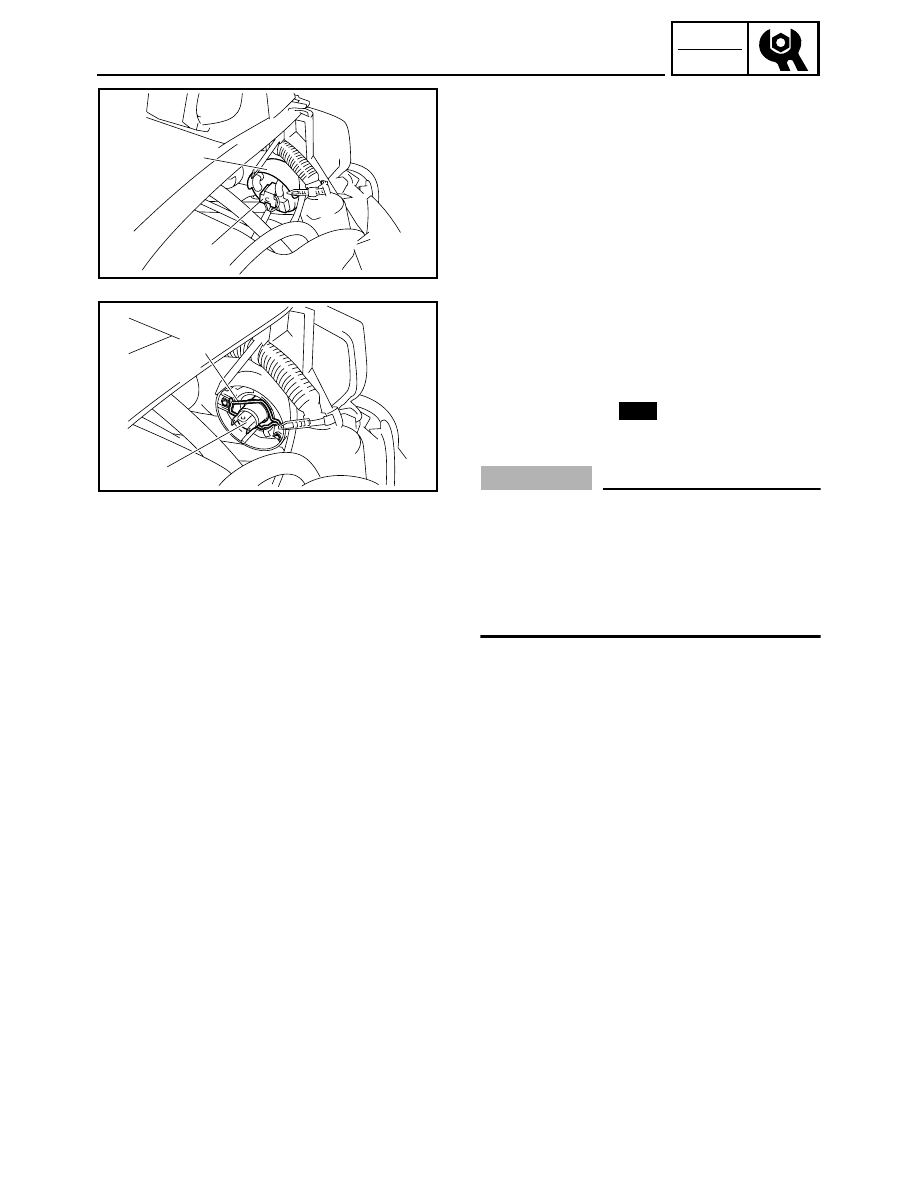
HEADLIGHT BULB REPLACEMENT
The following procedure applies to both of the
headlight bulbs.
1. Remove:
• Shroud
Refer to “COVERS” in CHAPTER 3.
2. Disconnect:
• Headlight coupler 1
3. Remove:
• Headlight bulb cover 2
4. Detach:
• Headlight bulb holder 3
5. Remove:
• Headlight bulb 4
6. Install:
• Headlight bulb
Secure the new headlight bulb with the head-
light bulb holder.
CAUTION:
Avoid touching the glass part of the headlight
bulb to keep it free from oil, otherwise the trans-
parency of the glass, the life of the bulb and the
luminous flux will be adversely affected. If the
headlight bulb gets soiled, thoroughly clean it
with a cloth moistened with alcohol or lacquer
thinner.
7. Attach:
• Headlight bulb holder
8. Install:
• Headlight bulb cover
9. Connect:
• Headlight coupler
10. Install:
• Shroud
Refer to “COVERS” in CHAPTER 3.
2
1
3
4
New