Snowmobile Polaris IQ (2007-2008 year). Manual - part 66


  Index      Snowmobiles / ATV     Snowmobile Polaris IQ - service manual 2007-2008 year


Search            


Content   ..  64  65  66  67   ..


Snowmobile Polaris IQ (2007-2008 year). Manual - part 66


9.16

Shocks

pressure in 5 PSI increments until the desired
performance level is achieved.

Again, always reset the shock body chamber pressure to
the factory specification charge.

If one shock appears to be too soft, place the vehicle on
flat, level ground. Stand on the sled, and rock the skis back
and forth to verify issue.

Determine if the shock is leaking or has leaked an oil, then
determine why. Look for shaft damage and replace the
shaft and seal if damage is found.

If no oil leaks are found, verify there are no gas leaks at the
charge ports. Replace the charge ports as required.

After inspecting both shocks, recharge both shocks to the
desired pressure settings and specifications.

SHOCK MAINTENANCE

Ryde FX Air 2.0 Shock Disassembly
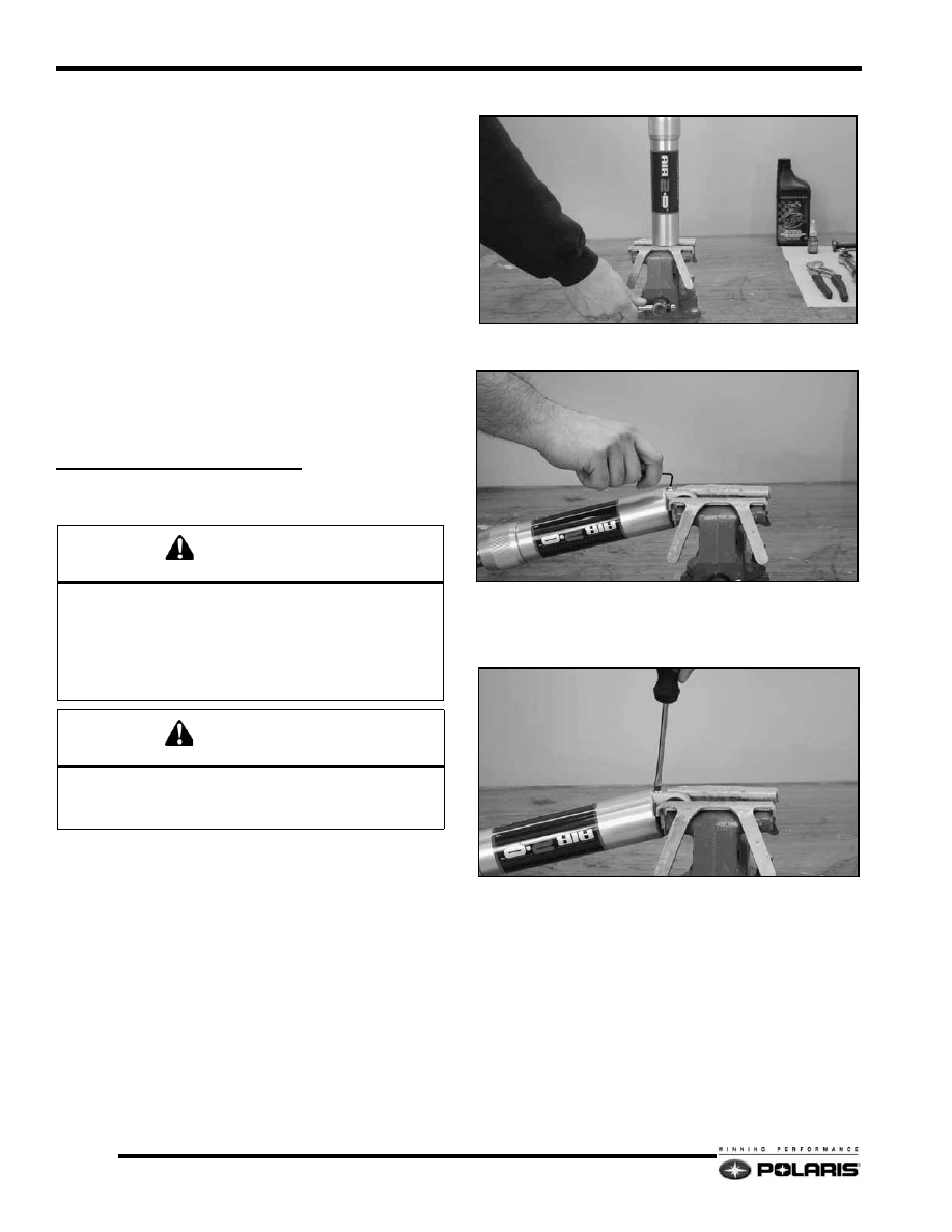
1.

Remove the shock from the snowmobile. Wash the entire
shock assembly in parts cleaner, then dry with compressed
air or a clean shop towel.

2.

Remove lower shock body mount eyelet components.

Secure shock in a soft-jawed table vise.

3.

Remove both small bottom head screws form each pressure
valve assemblies located at both ends of the shock.

4.

Using a flat-blade screwdriver, carefully loosen both
pressure valve assemblies counter-clockwise two full
rotations. Allow all of the nitrogen gas to fully escape past
each pressure valve assembly o-ring.

WARNING

Before servicing a gas shock it is important that all the 

gas pressure be discharged from the shock.

Nitrogen gas is under extreme pressure. Protective 

eyewear must be worn at all times to avoid risk of injury 

while servicing shocks or using compressed air.

CAUTION

Always clamp the lower mount of the shock in a vise. Any 

other method of securing the shock body may deform 

the shock body cylinder.

9.17

Shocks

9

5.

After all of the nitrogen gas has been allowed to escape
from the shock, remove both pressure valve assemblies.

6.

Using interlocking channel pliers, loosen and remove the
cylinder head assembly.

7.

Pour the oil out of the cylinder. Discard oil into an approved
container and dispose appropriately. Never reuse shock oil.

8.

Using compressed air, invert the large diameter cylinder
over a clean shop towel. Pressurize the cylinder to 90 psi
to remove the IFP from the cylinder. Account for the
floating piston, wear band, and o-ring.

9.

Place the 36mm piston (shock) rod upper mount in a soft-
jawed bench vise. Remove the piston valve and valve shim
assembly from the rod in the sequence of disassembly.

10. Remove the rod head assembly and spring from the rod

shaft.

11. Again, using compressed air, invert the rod shaft over a

clean shop towel. Pressurize the cylinder to 90 psi to
remove the IFP from the cylinder.  Account for the floating
piston and o-ring.

12. With the shock disassembled, inspect the following items:

• 36mm piston rod for straightness, nicks, or burrs.

• Cylinder head assembly / bearing.

• Inside of shock body for scratches, burs, or excessive 

wear.

• Teflon piston and IFP wear band for cuts, chipped or 

nicked edges, or excessive wear.

• O-rings for nicks, cuts, or cracks.

• Valve discs for kinks or waves.

9.18

Shocks

Ryde FX Air 2.0 Shock Assembly

1.

Place the 36mm piston rod upper mount in a soft-jawed
bench vise. Lubricate the internal IFP and o-ring with
shock oil.

2.

Install the internal IFP, flat-side / o-ring side first, into the
piston rod.

3.

Install the rod head assembly. Torque to specification.

4.

Install the compression and rebound valve shim stacks back
on to the piston valve assembly in the order they were
removed.

5.

Apply a small amount of Loctite 290 to the bolt threads.
Thread piston assembly into piston rod by hand.

6.

Torque bolt to specification.

7.

Apply a light film of grease to the 36mm rod assembly
pressure valve port counter bore where the pressure valve
assembly o-ring meets.

8.

Install pressure valve assembly and torque to specification.

9.

Pressurize the 36mm piston rod through the pressure valve
with nitrogen gas to the specified pressure.

NOTE: The internal IFP will be forced to the top of
the piston rod after cylinder is pressurized.

10. Secure the shock body lower mount in a soft-jawed bench

vise.

11. Thread the head onto the IFP locator tool and adjust the top

of the value indicator to the specified IFP measurement.

T 

T 

Piston Valve Bolt Torque

28 - 32 Ft.Lbs.

CAUTION

DO NOT OVER-TORQUE PISTON VALVE BOLT.

T 

Pressure Valve Assembly Torque

100 - 110 In.Lbs.

9.19

Shocks

9

12. Apply a thin layer of oil to the IFP, wearband, and o-ring.

Insert the IFP, o-ring side first, into the shock body.

13. using the IFP locator tool, slowly push the IFP down into

the cylinder. The IFP is set to the correct position when the
indicator knob makes contact with the shock body.

14. Install the pressure valve assembly into the valve port and

torque to specification.

15. Slowly fill the shock body with Ryde FX shock oil up to

the level of the outer threads.

NOTE: Allow the shock to stabilize for several
minutes and allow the air bubbles to escape to the
top.
Wrap the shock body with clean shop towels to
catch any shock oil spillage.

16. Invert the 36mm piston rod assembly and pour a small

amount of shock oil into the center of the locking piston bolt
until the oil flows back out of the hole.

17. Hold a finger over the bolt hole, then carefully insert the

piston rod into the shock body cylinder. Slightly oscillate
the piston rod to allow the piston to enter the shock body
bore.

18. Slowly push the piston rod into the shock body until the

cylinder head assembly bottoms on the cylinder
counterbore. Slight up and down movement may be
required to allow all air to pass through the piston assembly.

19. Using interlocking channel pliers, securely tighten the

cylinder head on the shock body.

T 

Pressure Valve Assembly Torque

100 - 110 In.Lbs.


Content   ..  64  65  66  67   ..