Snowmobile Polaris IQ (2007-2008 year). Manual - part 34


  Index      Snowmobiles / ATV     Snowmobile Polaris IQ - service manual 2007-2008 year


Search            


Content   ..  32  33  34  35   ..


Snowmobile Polaris IQ (2007-2008 year). Manual - part 34


5.14

Engine and Cooling Systems

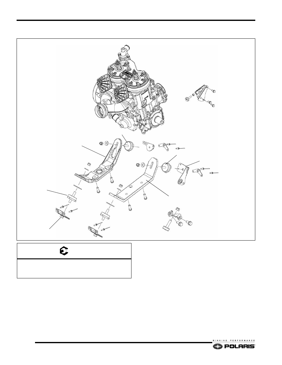
2007 IQ 600 CFI Engine Mounting

NOTE:  Use an engine mount socket, PN: 2871989 to
remove the engine mounts from the bulkhead.

ISOLATOR

TORQUE STOP

ENGINE ASSEMBLY

CLINCH PLATE

ENGINE MOUNT

ENGINE MOUNT

ENGINE MOUNT

RH ENGINE STRAP

LH ENGINE STRAP

ENGINE MOUNT BRACKET

A

A

A

A

A

A

A

A

B

C

C

C

C

T 

A = 28 Ft.Lbs. (38 Nm)
B = 15 Ft.Lbs. (20 Nm)
C = 30 Ft.Lbs. (41 Nm)

5.15

Engine and Cooling Systems

5

2008 IQ Carbureted Engine Mounting

NOTE:  Use an engine mount socket, PN: 2871989 to
remove the engine mounts from the bulkhead.

CLINCH PLATE

ENGINE MOUNT

RH ENGINE STRAP

SPACER

ENGINE MOUNT

TORQUE STOP

ENGINE MOUNT BRACKET

LH ENGINE STRAP

ENGINE MOUNT

ENGINE ASSEMBLY

A

A

A

A

A

A

B

C

C

C

C

A

T 

A = 28 Ft.Lbs. (38 Nm)
B = 15 Ft.Lbs. (20 Nm)
C = 45 Ft.Lbs. (61 Nm)

5.16

Engine and Cooling Systems

2007 700 CFI / 2008 IQ CFI Engine Mounting

NOTE:  Use an engine mount socket, PN: 2871989 to
remove the engine mounts from the bulkhead.

CLINCH PLATE

ENGINE MOUNT

BOTTOM ENGINE MOUNT

ENGINE MOUNT

ENGINE MOUNT

ENGINE MOUNT BRACKET

TORQUE STOP

ENGINE ASSEMBLY

RH ENGINE STRAP

LH ENGINE STRAP

UPPER ENGINE MOUNT

A

A

A

A

A

A

C

C

C

C

B

A

T 

A = 28 Ft.Lbs. (38 Nm)
B = 15 Ft.Lbs. (20 Nm)
C = 30 Ft.Lbs. (41 Nm)

5.17

Engine and Cooling Systems

5

ENGINE COMPONENT ASSEMBLIES

600 HO Carbureted Cylinders / Cylinder Head

Disassembly / Assembly Process

1.

Remove the coolant from the engine using a siphon, wet/
dry vac, or drain pan.

2.

Remove the air box, exhaust pipe and resonator from the
engine compartment.

3.

Remove the high tension wires and spark plugs from the
cylinder head.

4.

Remove the thermostat housing outlet cooling hose from
the housing.

5.

Loosen all, then remove all head cover fasteners. Clean the
fastener threads to remove any thread locking residue.

6.

Discard the head cover and cylinder head o-rings. Always
use new o-rings during assembly.

7.

Inspect the cylinder head / combustion domes for any
damage. Measure cylinder head flatness. Replace cylinder
head if required.

8.

Loosen all, then remove the cylinder bolts. Clean the bolt
threads to remove any thread locking residue.

9.

Carefully pull each cylinder upwards taking care not to
drop the piston and rod abruptly against the crankcase.

10. Remove the cylinder base gaskets. Use a gasket scraper to

clean the gasket residue from the crankcase and cylinder
bases.

11. Inspect the cylinder walls. Nicasil cylinders can only be

lightly honed. Damage that cannot be removed with a light
hone requires cylinder replacement or re-lining.

12. The assembly process is the reverse of disassembly.

13. Always use new gaskets and o-rings during assembly.

Liberally coat the inside of each cylinder and the outside
of each piston with Polaris two-stroke engine oil.

14. When installing a piston into a cylinder, verify each piston

ring opening is located at each piston ring locating pin.
Squeeze the top ring, then carefully slide the cylinder over
the compressed ring. Do the same with the bottom ring.

15. Follow the torque specifications and torque sequences

located at beginning of chapter when tightening fasteners.

HEAD COVER

WASHERS

CYLINDER HEAD O-RINGS

CYLINDERS

CYLINDER BASE GASKETS

CYLINDER HEAD

HEAD COVER O-RINGS

THERMO SENSOR

KNOCK SENSOR

THERMOSTAT

GASKET

THERMOSTAT
HOUSING

BLEED SCREW

A

B

C

D

E

F

T 

A = 70 In.Lbs. (8 Nm)
B = 9 Ft.Lbs. (12 Nm) - Apply Loctite 242
C = 25 Ft.Lbs. (34 Nm) - Apply Loctite 242
D = 18 Ft.Lbs. (24 Nm) - Apply Pipe Sealant
E = 168 In.Lbs. (19 Nm) - Clean and Dry
F = 37 Ft.Lbs. (50 Nm)


Content   ..  32  33  34  35   ..