Snowmobile Polaris IQ (2007-2008 year). Manual - part 27
4.26
Fuel Systems
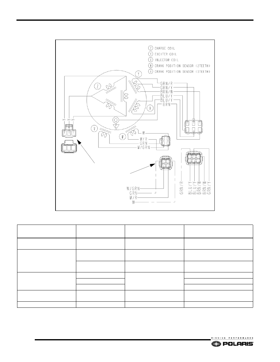
Stator Assembly
Stator Specifications
ITEM
COLOR
SYSTEM FUNCTION
RESISTANCE
+/- 15% @68
°
F (20
°
C)
CHARGE / LIGHTING COIL
YELLOW
CHASSIS / BATTERY
POWER
YEL TO YEL = 0.13
Ω
NO CONTINUITY TO GROUND
CRANK POSITION SENSOR
(CPS)
GRN to WHT/GRN
Crank Position Sensor (5
Tooth) Ignition timing.
GRN to WHT/GRN = 190
Ω
WHT to WHT/RED
Crank Position Sensor (2
Tooth) Locates TDC and RPM.
WHT to WHT/RED = 190
Ω
COILS
GRN/RED
Exciter Coil - Powers the
Ignition Coils / ECU
GRN/RED to GRN/YEL = 15
Ω
GRN/YEL
GRN/RED to BRN/WHT = 30
Ω
BRN/WHT
BRN/WHT to Ground = 0
Ω
INJECTOR POWER COIL
BLU/YEL TO BLU/YEL
Supplies power to fuel
injectors.
BLU/YEL to BLU/YEL = 2.4
Ω
ENGINE GROUND
BROWN
ENGINE GROUND
0
Ω
CRANK POSITION
SENSORS
REG REC