Index Snowmobiles / ATV Snowmobile Polaris Two Stroke - service manual 2007 year
Search
Content .. 68 69 70 71 ..
Snowmobile Polaris Two Stroke (2007 year). Manual - part 70
11.17
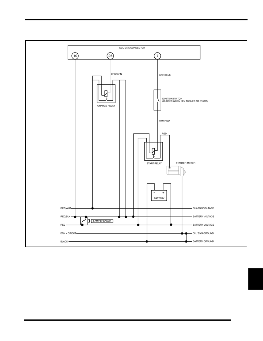
BATTERY & ELECTRICAL SYSTEMS
11
System Schematic - 600 / 700 CFI