Snowmobile Polaris Two Stroke (2007 year). Manual - part 53
8.15
FRONT SUSPENSION & STEERING
8
4.
Replace snap ring (22).
5.
Install spindle.
6.
Install the ski(s).
UPPER / LOWER CONTROL ARM REMOVAL
1.
Remove the spindle(s) and shock(s).
2.
Remove the upper and lower control arm(s) bulk head bolts
(1,6).
3.
Remove the upper or lower control arm (10,20) and remove
all pivot bushings (5,9), and all pivot shafts (3, 7).
Upper / Lower Control Arm Installation
1.
Replace the upper or lower control arm bushings (5,9) and
pivot shafts (3, 7) in the control arm(s).
2.
Replace the upper or lower control arm(s) into the
bulkhead.
3.
Replace the upper or lower control arm bolts (1,6). Torque
to 40 ft-lb (54 N-m).
NOTE: A spacer washer (2) is located on the lower
rearward mounting area, and should be located at
the bolt head.
STEERING
INSPECTION
Prior to performing steering alignment, inspect all steering and
suspension components for wear or damage and replace parts as
necessary. Refer to steering assembly exploded views in this
chapter for identification of components and torque values of
fasteners. While disassembling, make notes of what direction a
bolt goes through a part, what type of nut is used in an
application, in which direction do the steering arms go on - weld
up or weld down, etc.
Some of the fasteners used in the IFS are special and cannot be
purchased at a hardware store. Always use genuine Polaris parts
and hardware when replacing front end components. Review
steering adjustment guidelines before making adjustments.
The following components must be inspected at this time.
• Tie rods and tie rod ends
• Control arms and control arm ends
• Torsion bar and bushings / linkage (where applicable)
• Handlebars and steering post assembly
• Spindles and bushings
• Skis and skags
• Pitman arms / Idler arms
• Steering arms
• A-arms and bushings
• Shock absorbers, shock mounts, springs
• All related fasteners - check torque. Refer to steering
exploded views at the beginning of this section.
• Grease all fittings.
Always follow rod end engagement guidelines. Maximum
setup width must be checked whenever front suspension
components are adjusted or replaced.
Alignment Bar Specifications
• DIAMETER: .623”-.625” (15.824-15.875mm)
• LENGTH: 45” (114.3cm)
• MATERIAL: C-1018
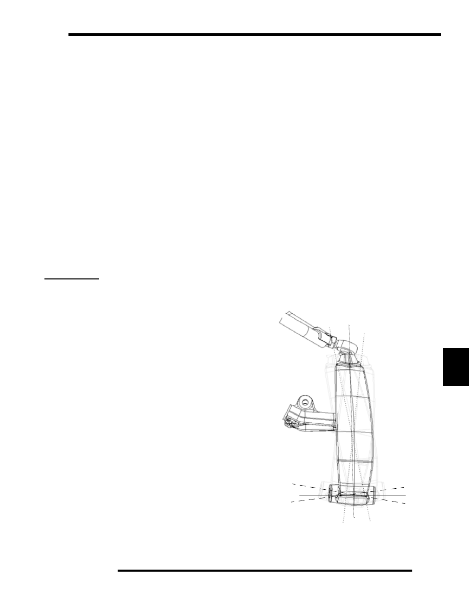
Camber Definition
The following definitions of camber use automotive
terminology to describe positive and negative positions.
• 0 = Neutral camber. The spindle is 90° (perpendicular)
to the ground.
• + = Positive camber. The bottom of the spindle is
canted inward toward the chassis.
• - = Negative camber. Spindle bottom is canted outward
from the chassis.
+
-
0
-
0
+