Snowmobile Polaris Two Stroke (2007 year). Manual - part 45
7.7
FINAL DRIVE/BRAKES
7
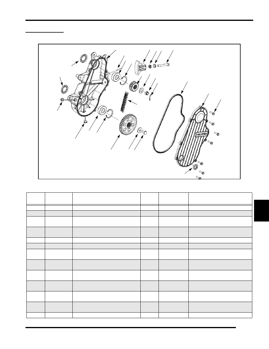
CHAIN CASE
Exploded View
Chaincase
ITEM
DESCRIPTIO
N
TORQUE SPECIFICATION / NOTES
ITEM
DESCRIPTION
TORQUE SPECIFICATION /
NOTES
A
Cover bolts
8 ft-lb(11N-m) N
Breather
roll
pin
B
Chaincase cover
O
Chaincase
C
Cover gasket
make sure that the gasket is not pinched
during assembly
P
Upper seal
Install so that the lip is facing the
chaincase
D
Cotter pin
bend the ends over the nut flats when
installing
Q
Lower seal
Install so that the lip is facing the
chaincase
E
Jackshaft nut
50 ft-lb (62.5N-m)
R
Fill plug
F
Washer
S
Drain plug
8 ft-lb (11N-m)
G
Top sprocket
Install so that the shoulder is facing the
bearing
T
Lower bearing
Loctite 680 when assembled
H
Chain tensioner
adjuster
Torque only finger tight during assembly
U
Lower c-clip
Install so that the chamfered edge is
facing the bearing
I
Tensioner lock
nut
V
Chain
J
Fastener Seal
Thread this onto the adjuster bolt during
assembly
W
Lower sprocket
Install so that the shoulder is facing the
bearing
K
Tensioner
Assembly
X
Washer
L
Upper c-clip
Install so that the chamfered edge is facing
the bearing
Y
Lower sprocket
retaining bolt
19 ft-lb (26N-m)
M
Upper bearing
Loctite 680 when assembled
Z
Sight glass
Only remove if replacing
A
B
C
D
E
F
G
H
I
J
K
L
M
N
O
P
Q
R
S
T
U
V
W
X Y
Z
image depicts 8.373 chaincase, your chaincase may vary slightly