Snowmobile Polaris PRO X (2003 year). Manual - part 39


  Index      Snowmobiles / ATV     Snowmobile Polaris 440 PRO X Fan, 440 PRO X, 600 PRO X, 700 PRO X, 800 PRO X - service manual 2003 year


Search            


Content   ..  37  38  39  40   ..


Snowmobile Polaris PRO X (2003 year). Manual - part 39


CLUTCHING

4.24

Spider Roller Removal

1.

Remove spider buttons using button removal tool.

Remove shims (if any are installed) and note location.
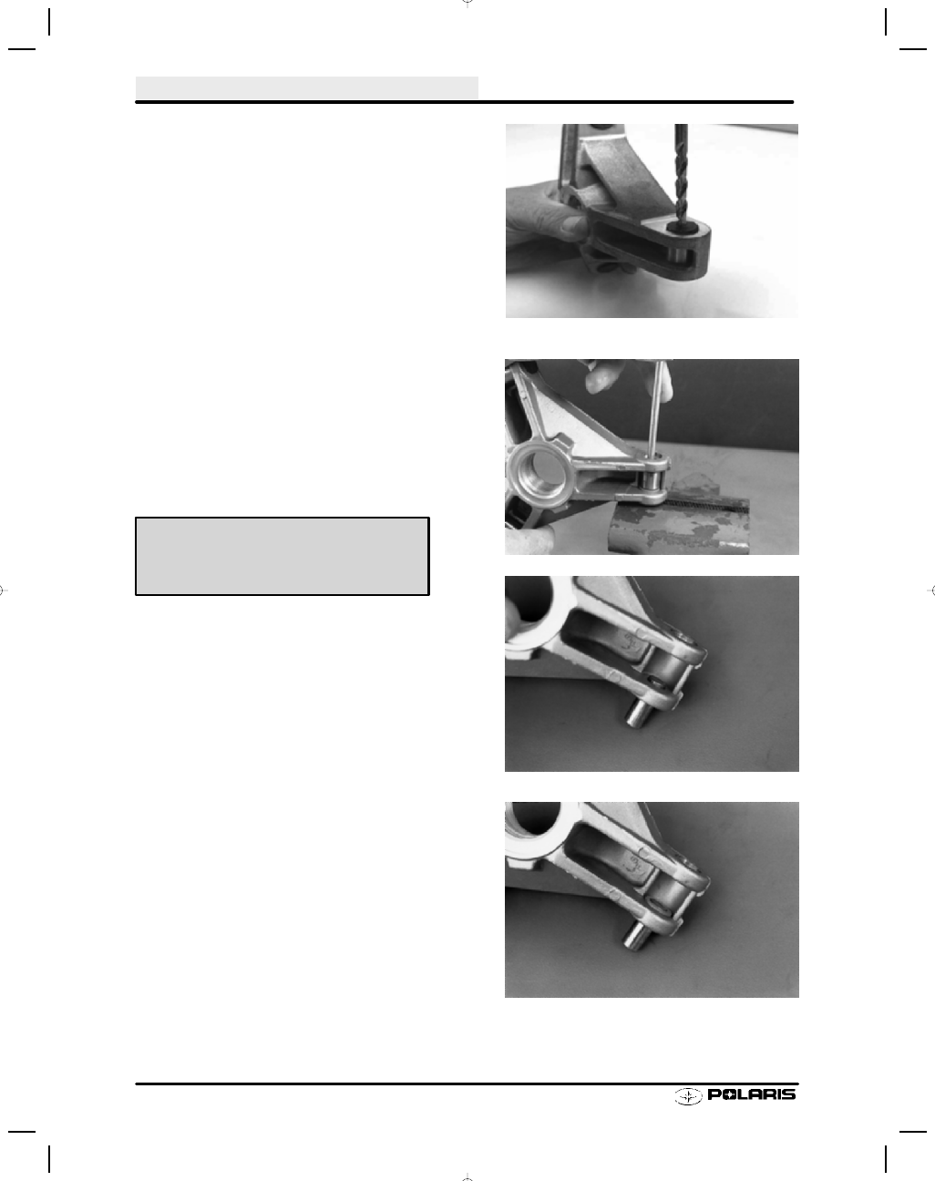
NOTE:The drive clutch spider buttons for the 800
twin 
cylinder domestic engines are less exposed
than typical. It will not be possible to remove the
buttons with the traditional spider button removal
tool.

S

Using a 5/16” drill bit, drill a hole through the center
of the button until the drill bit hits the pin (approxi-
mately 3/16” (5 mm).

S

Place Clutch Pin Tool PN 2870910 in the 5/16” hole
you drilled.

S

Using an arbor press, press the pin and opposite but-
ton out. Place a 5/16” bolt or rod in the opposite hole
to press the button out that you drilled through. Use
button PN 5434188 as your replacement buttons.

2.

Place spider on a vise or in an arbor press. Using a
pin punch, drive out the roller pin.

Roller Installation

1.

Start a replacement roller on each leg, driving a pin in
.100

s-.125s (.25-.32 cm) beyond the first land of the

spider leg (A). Remove any aluminum burrs from pin
protruding from spider.

2.

Install one washer onto pin.

800 Twin clutch only

Spider Button Removal Tools
PN 2870910 (800 Twins)
PN 2870985

CLUTCHING

4.25

Roller Installation, Cont.

3.

Place roller on pin as it protrudes from first land.

4.

Place a second washer on other side of roller.

5.

Install service tool.

6.

Place spider on a vise anvil and drive roller pin
through to second land of spider.

CAUTION:

Use care to start the pin straight. Aluminum burrs could
pass through into the roller bushing causing it to bind and
stick. Also use care to make sure the roller remains
aligned when the pin is driven through. The roller bushing
could be damaged causing premature wear and roller fail-
ure.

Spider Button Shimming

1.

Determine how many shims are to be used.

NOTE: A shim kit is available which contains an assort-
ment of shims, including .002

s, .005s, and .010s.

Shim Kit PN 2200387

CLUTCHING

4.26

Spider Button Shimming, Cont.

2.

Measure the dimension between towers at the lower
half of the towers as shown.

3.

Install spider buttons using a soft face hammer.

4.

Record width of spider buttons on each leg.

5.

Add shims beneath trailing side spider button to
obtain specified button-to-tower clearance when
assembled.

Use Dial
Caliper

Measure tower
width at bottom
of travel

Measure each
leg and record

Button to Tower Clearance -

P-85 = .002

(.05 mm)

CLUTCHING

4.27

Drive Clutch Assembly

1.

Place the correct number of spacer washers
beneath the spider. Spacer PN 5132542 is a stepped
washer that can be placed in addition to one of the
above shims for precise shimming.

2.

Assemble clutch making sure “X” marks on movable
sheave and spider, or reference marks made before
disassembly are aligned to achieve proper balance.

NOTE: If belt to sheave clearance is being changed by
adding or removing washers from under the spider, and
the sheaves were marked before disassembly, follow in-
dexing procedure on page 4.28.

3.

Torque spider to specification.

4.

Torque jam nut to specification (P-85 Clutches).
Install weights with weight pin nut on trailing side.
Use new nuts to ensure proper retention. Torque nut
to 30 in. lbs.

Marks

Spider Torque - P85 (all except 800 RMK)

Spider Removal Tool

PN 2872987

200 ft. lbs. (276 Nm)

Spider Torque - P85 (800 RMK)

Spider Removal Tool

PN 2872987

230-250 ft. lbs. (318-346 Nm)

Jam Nut Torque - P85 (except 800 RMK)

Jam Nut Tool

235 ft. lbs. (325 Nm)

PN 2870338

Weight Pin Nut Torque

30 In. Lbs. (3.4 Nm)

Jam Nut Torque - P85 (800 RMK)

200 ft. lbs. (277 Nm)


Content   ..  37  38  39  40   ..