Snowmobile Polaris (2006 year). Manual - part 21


  Index      Snowmobiles / ATV     Snowmobile Polaris - service manual 2006 year


Search            


Content   ..  19  20  21  22   ..


Snowmobile Polaris (2006 year). Manual - part 21


3.20

MAINTENANCE

TRACK ALIGNMENT

NOTE:  Track alignment affects track tension. 
Misalignment of the track will cause excessive wear 
to the track, rail slides, and rail.

NOTE:  Excessive rail slide wear occurs due to 
running in inadequate snow conditions.

Periodically check that the track is centered and running 
evenly on the slide rails. Misalignment will cause excessive 
wear to the track and slide rails.

1.

Safely lift and support the rear of the snowmobile off the
ground.

2.

Rotate the track by hand to check for any possible damage.

3.

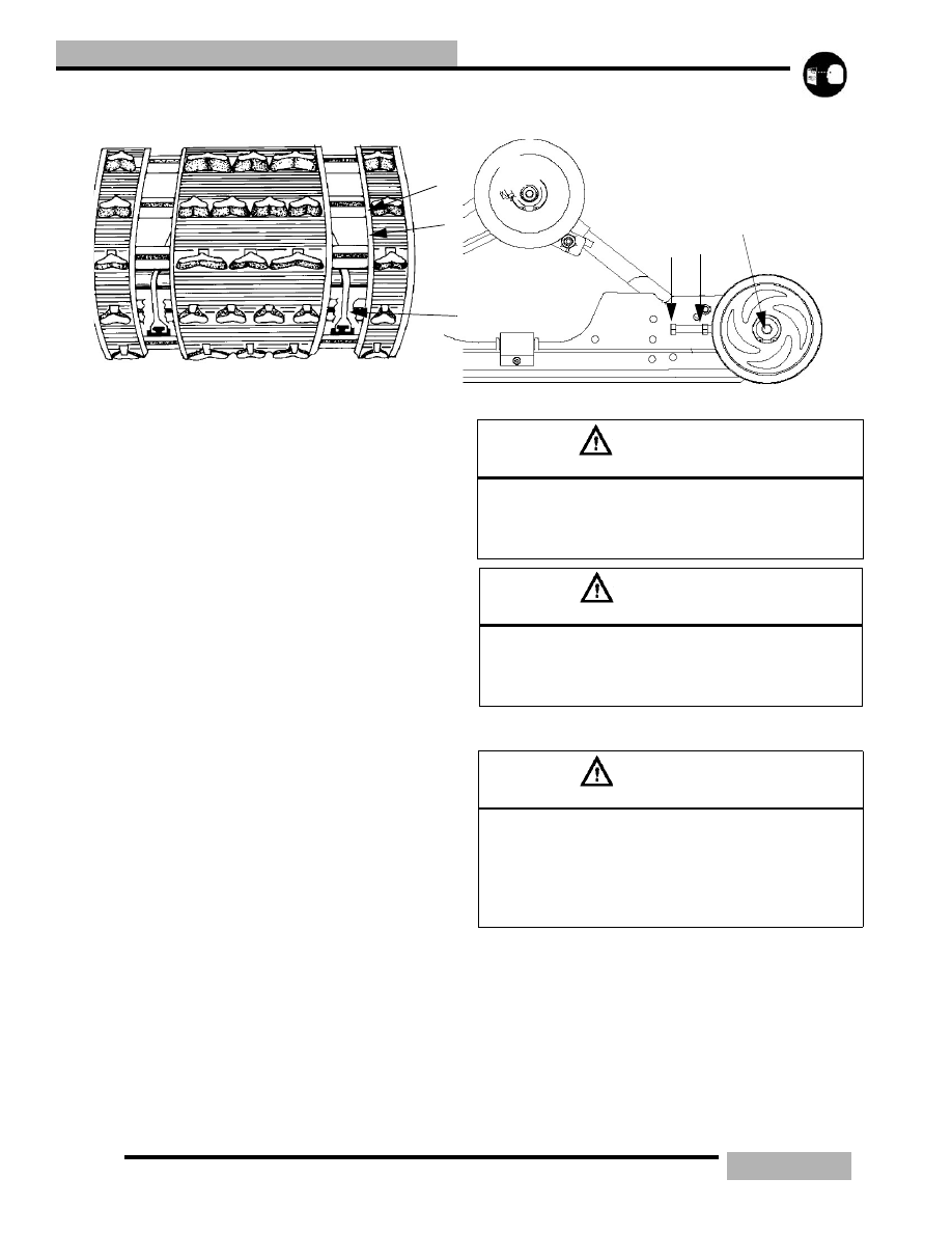
Inspect the track rods (A) carefully and examine the track
along the entire length of each rod, bending the track edge
and inspecting it for breakage. If any rod damage is found,
the track should be replaced.

4.

Warm up the track by starting the engine and apply a small
amount of throttle so the track runs slowly at least five
complete revolutions.

5.

Stop the engine and turn the ignition off.

6.

Inspect track alignment by carefully looking through the
track window (B) to make sure the rails (C) are evenly
spaced on each side. 

7.

Before any adjustments are made loosen up the rear idler
shaft (F). 

8.

If the track runs to the left, loosen the left locknut and
tighten the left adjusting bolt (D). If the track runs to the
right, loosen the right locknut and tighten the right
adjusting bolt. It may be necessary to check this with the
engine rotating the track. Be sure to SHUT THE
MACNINE OFF before making any further adjustments.

9.

After any adjustments are complete, be sure to torque the
locknuts (E) to 35 ft-lb (48Nm).

10. Torque both idler shaft bolts (F) to 35 ft-lb (48Nm).

TRACK LUBRICATION

The slide rail needs snow for lubrication and cooling. 
Excessive wear indicates insufficient lubrication. A new rail 
slide can cause faster heat build-up in limited lubrication, 
resulting in excessive wear.

NOTE:  If excessive rail slide wear occurs due to 
poor snow conditions additional wheel kits can be 
added.

A

B

C

D

E

F

WARNING

Broken track rods can cause a rotating track to come off 

the machine. Never operate or rotate a damaged track 

under power with a broken rod. Serious injury or death 

may occur.

WARNING

When performing the following checks and adjust-

ments, stay clear of all moving parts to avoid personal 

injury. Never make any adjustments with the engine 

running, as serious personal injury can result.

WARNING

Operating with insufficient lubrication between the rail 

slide and track guide clips can cause track failure, loss 

of vehicle control and loss of braking ability, which can 

result in serious injury or death. Avoid operating vehicle 

on ice and other surfaces that have little or no snow 

conditions.

3.21

MAINTENANCE

NOTE:  Track damage of failure caused by operation 
on ice or under other poor lubrication conditions will 
void the tracks warranty.

TRACK TENSION

Track tension is critical for maintaining correct suspension 
operation. If the track tension is too loose it may cause the 
track to slip or “ratchet” on the drive shaft drivers and cause 
the track and rear suspension durability problems. If the track 
is too tight the track will wear down the rail slides, reduce top 

speeds, cause rear suspension vibration and cause track and 
rear suspension durability problems.

1.

Lift the rear of the machine and place a jack stand or secure
the rear of the machine so that the track is off of the
ground.

2.

Start the engine and slowly let the engine turn the track
over. This will warm up the track for a correct
measurement.

3.

Shut off the engine.

4.

Place a 10 lbs. (4.54kg) weight at point (A). Point (A) is
16” (41cm) ahead of the rear idler shaft (E).

5.

Measure the distance (D) between the rail slider and the
track. This measurement should fall with in the
measurement range for the appropriate vehicle.

6.

If adjustment is needed, loosen up the lock nuts (B) on
each side.

7.

Loosen up the idler shaft bolts (F).

8.

Turn each adjuster bolt (C) toward the idler wheel
(clockwise) if you need less of a measurement. Tun the
adjuster bolt (C) toward the front of the sled
(counterclockwise) if you need a greater measurement.

9.

When you achieve the correct tension listed below, torque
the lock nuts (B) and idler shaft bolts on each side to 35 ft-
lb (48Nm).

NOTE:  Track alignment affects track tension. 
Misalignment will cause excessive wear to the track 
and slide rails. Excessive slide wear will appear on 
units with the track tension set too tight (or below 
measurement specification).

o

B

C

A

D

16”(41cm)

E

TRACK

F

Table 3-4: Track Tension Data

SUSPENSION

MEASUREMENT

EDGE / EDGE RMK / SWITCHBACK/ IQ RMK / IQ 

SWITCHBACK

3/8” - 1/2” (1 - 1.3cm)

IQ FUSION

7/8” - 1 1/8” (2.2 - 2.9cm)

M-10

7/8” - 1 1/8” (2.2 - 2.9cm)

M-10 128”

7/8” - 1 1/8” (2.2 - 2.9cm)

M-10 136”

7/8” - 1 1/8” (2.2 - 2.9cm)

EDGE TOURING / WIDETRAK

3/4”- 1” (1.9 - 2.5cm)

EDGE 136”

7/8” - 1 1/8” (2.2 - 2.9cm)

120 PRO X

3/8

” 

(.95cm)

3.22

MAINTENANCE

OIL PUMP ADJUSTMENT

1.

On some engines the oil pump is located under the intake
boots and you may have to remove the air box and may
need to unplug the CDI box and coils.

2.

Verify carburetor synchronization see “THROTTLE
VALVE SYNCRONIZATION” on page 4.13.

3.

Loosen the carburetor boot adapters and carefully move
them so that you can see and adjust the oil pump cable.

4.

Verify that the oil pump alignment lines are aligned at the
point where the carburetor slides begin to raise from their
resting positions.

5.

If they are not aligned make the necessary adjustments by
adjusting the oil pump cable. In small increments, loosen
the lock nut that is closest to the oil pump (A). and move
the mark that is on the oil pump arm by tightening or
loosening the adjustment nut (B) as needed to get the line
to the desired position (550 has alignment marginal at
wide open throttle).

6.

Lock the lock nut (A).

7.

Verify that the oil pump marks line up as outlined in step

4.

8.

Re-install carburetors, air box and plug in the CDI and
coils if they were taken off in step 1.

9.

Check idle to specification and adjust if needed.

NOTE:  A mirror may aid in checking the oil line 
markings.

HEADLIGHT ADJUSTMENT

The headlight can be adjusted for vertical aim using the 
following procedure:

1.

Place the snowmobile on a flat level surface with the
headlight approximately 25 feet (7.6m) from a wall.

2.

With a tape measure, measure the center line of the
headlight on the vehicle. You may have to eye up the
center line. 

3.

Mark the headlight center line distance that you found on
step 4, and mark it on the wall that the machine is facing.

4.

Apply and lock the parking brake.

5.

Start the engine.

6.

Set the headlight switch to HIGH beam.

7.

With the rider in full gear and the sled at ride height
continue to step 8.

8.

Observe the headlight aim. The most intense part if the
headlight beam should be aimed 2”(5.1cm) below the
mark placed on the wall in step 3.

NOTE:  On Edge models you can adjust the 
headlight by turning the adjusting knob that is 
located on the under side of the hood, just below the 
head lamp opening.

3

4

A

B

C

600 Liberty

o

2”(5.1cm)

25ft.(7.6m)

LAMP CENTER LINE

WALL

EDGE headlight adjustment knob

3.23

MAINTENANCE

NOTE:  On IQ models you can adjust the headlight 
by turning the adjustment knob that is located on the 
top side of the hood, next to the MFD gauge.

HANDLEBAR ADJUSTMENT

1.

Remove the handle bar cover slides (A) and then the dart
clips (B) that holds on the handle bar cover (C).

2.

Remove the handle bar cover.

3.

Remove the console covers (D) if equipped.

4.

Loosen the handle bar block bolts (E) and nuts (F).

5.

Rotate the handle bar (G) in the desired position.

6.

While holding the handlebar in the desired position tighten
the handle bar block bolts and torque to 12 ft-lb (16Nm)
starting with the front bolts.

7.

Replace the console covers (if equipped), handle bar cover,
handle bar cover slides, and dart clips.

HANDLEBAR RIDING POSITION 
ADJUSTMENT (Rider Select only)

On the IQ vehicles you have the option of seven (7) different 
riding positions.

1.

While sitting in the riding position on the vehicle, press
down on the adjustable steering lever (A).

2.

Adjust the handle bar (B) position to the desired position
and let go of the steering lever.

3.

Push handle bars forward and then pull backward on them
to verify that the position is locked.

WARNING

Improper adjustment of the handlebars, or incorrect 

torquing of the of the adjuster block can cause limited 

steering or loosening of the handlebars resulting in a 

loss of control situation.

IQ adjustment knob

A

B

C

D

F

E

G

12 (16)

HANDLEBAR ROTATING ADJUSTMENT

WARNING

Do not attempt to adjust the riding position while vehi-

cle is in motion. Loss of steering may result in personal 

injury or death.

A

B

IQ RIDING ADJUSTMENT


Content   ..  19  20  21  22   ..