Kincaid 8xp. Manual - part 6
 

  Index      Combines     Kincaid 8xp Combine Harvester - service manual 2012 year


Search            


Content   ..  4  5  6  7   ..


Kincaid 8xp. Manual - part 6


- 27 -

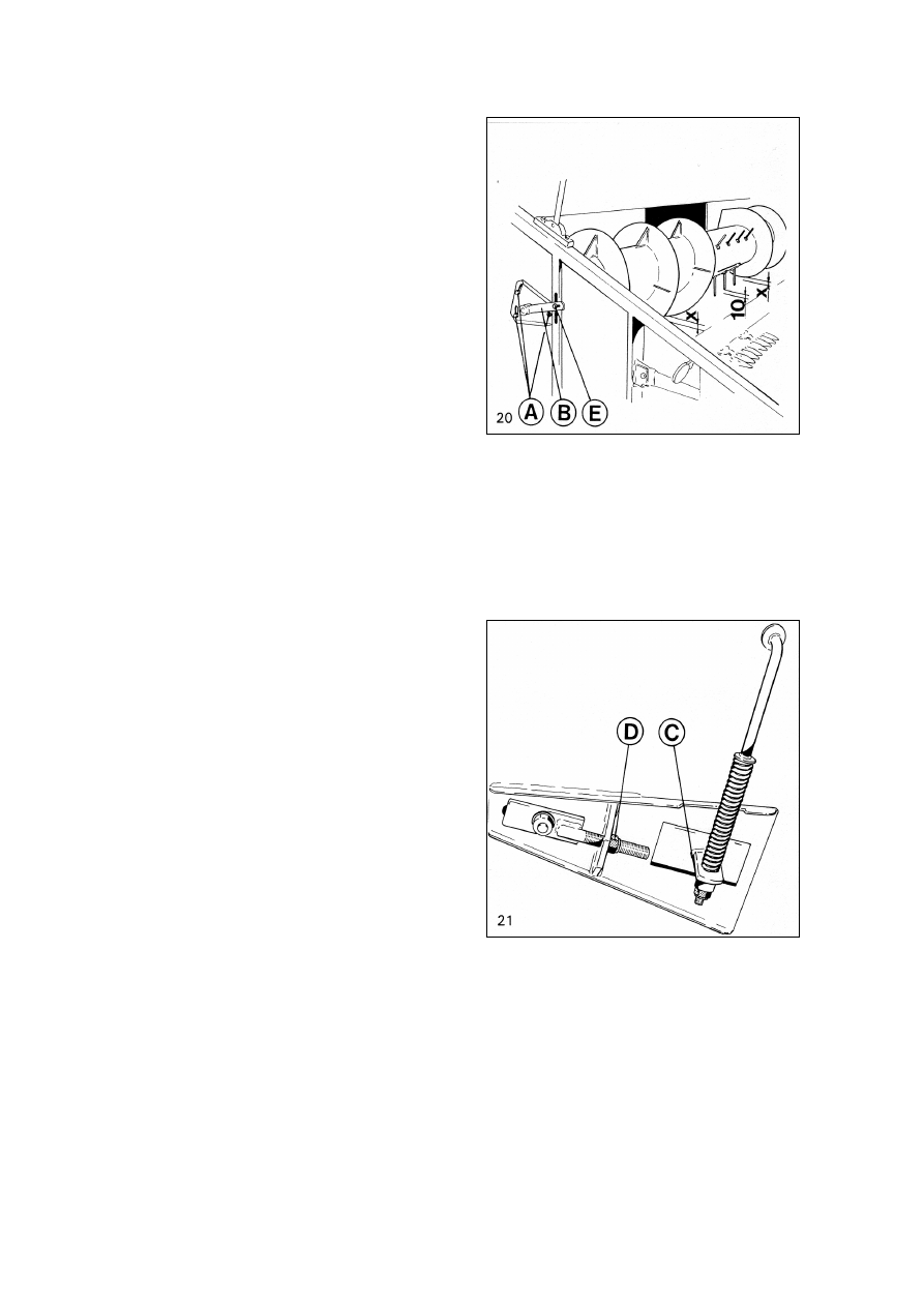
Table Auger (Fig. 20) height 

and

finger positions are adjustable

Adjust the table auger vertically to suit the

lot of straw in the crop being threshed.

E.g. in strong rye and turnip rape adjust

the clearance between auger and cutting

table wider, approx. 30 to 40 mm.

To adjust, loosen screws A on both ends

of cutting table and the table auger can

be lifted or lowered as required. Clearance

between table auger and bottom has to be 

the same on both ends of the table. The 

normal clearance is 15 mm. After moving 

table auger, check feed finger adjustment 

and drive belt tension.

Feed finger position is adjusted, when

screw E has been loosened, with lever B on

the right and end of the cutting table.

Minimum acceptable clearance between

the bottom and finger tips is 10mm.

Crop Elevator Chain (Fig. 21)

correct height and tension

The elevator has a fixed top roller and a 

floating bottom roller to enable the elevator to

smooth out the flow of crop to the cylinder

and to handle a fluctuating feed.

Adjust the clearance between the bottom

roller and the bottom of the elevator housing

by the screws C. Correctly adjusted, there

should be a clearance of 0 to 5 mm between

the lowest slats and the housing.

The elevator chain is adjusted with screws D. 

Check the tension through the inspection

door in the top of the elevator housing. The

tension is correct when the deflection 

midway between the top and bottom rollers is 

approx. 50 mm.

The bottom of the crop elevator can be

adjusted depending of the crop harvested.

For cereal and small seed it is kept in upper

position for good cleaning. For corn it can

be lowered to avoid grain damaging.

22

- 28 -

Table Auger and Crop Elevator

Reverse Drive (Fig. 22) 

eliminates

blockage on the table

Blockage in crop feed might stop the table

auger and crop elevator. This can be cleared 

by running them backwards. To do this, 

disengage the drive to the table with the 

pedal and press the reverse switch A. The 

table auger and elevator will rotate in reverse 

direction, clearing the blockage.

NOTE! The reversing will only

operate when the table drive have

been disengaged and the engine is

running.

Cutting Table (Figs. 23 to 26)

Throw-out clutch and supporting

The throw-out clutch for the threshing and

feeding mechanism is controlled by a foot

pedal on the right-hand side of the operator’s

platform. Press the front of the pedal to 

disengage the drive mechanism and press 

the rear of the pedal to re-engage the 

mechanism.

CAUTION: The cutting mechanism 

disengaged by the pedal can start running 

when, for instance, feeding disorders are 

eliminated from the table. Therefore, always 

stop the engine before any work is carried 

out on the table.

Before repairing and maintenance beneath

the table, raise it to its full height and lock

the support over the ram by means of the

lever B, Fig. 23, on the left-hand side of the

feed conveyor.

Do not use the cutting table

support during transportation.

26

- 29 -

The table height is controlled 

by switch A, Fig.24. Cutting 

height is shown on the scale, 

fig. 25.

The cutting table is eased using a gas

accumulator, and the easing pressure is

shown on gauge A, fig. 26. With the needle 

in the green field of the gauge, the table fully

rests on the gas accumulator. When lowering

the table onto the ground, the easing

effect of the gas accumulator decreases and

the needle goes to the red field. The farther

red the needle goes, the more heavily the

table lies against the ground, in which case

soil or stones get easily onto the table and

damage it.

When threshing laid-down crops, adjust

the table height so that the needle is in the

green field or on the border between the

green and red where the easing effect of the

gas accumulator is still sufficient.

When necessary, the colour scale on the

table pressure gauge can be adjusted by

turning the glass. The needle shall be in the

green field, approx. 5 mm from the red field

when the cutting table is off the ground at

the height of approx. 20 - 30 cm.

29

- 30 -

Engage Threshing Mechanism 

at engine idling speed only 

(Fig. 28)

Engage the threshing mechanism with lever

A. Then the threshing cylinder, straw walkers,

grain pan, shaker shoe, grain elevator

and straw cutter are started.

NOTE! Engage and disengage the threshing

mechanism at engine idling speed only.

Threshing Cylinder (Fig. 29)

Stepless control of cylinder speed

The speed of the threshing cylinder can be

changed steplessly with switch C. The speed 

can only be changed with the threshing 

mechanism running. Cylinder speed is 

displayed in gauge A on the instrument 

panel with change switch B in the cylinder 

position. Recommended settings for the 

most common crops are displayed on the 

cab window.

Concave (Fig. 30 and 31)

Adjusting of the clearance

The clearance between the threshing 

cylinder and concave is steplessly adjusted 

by means of regulating wheel A on the right 

hand side of the operator’s platform. Turn the 

wheel anticlockwise for wider clearance and 

clockwise for smaller clearance. The needle 

on the scale B gives the clearance C, that is 

the distance in mm between the first concave 

beater and cylinder beater. Fig. 30

The control mechanism has been designed

to keep the ratio between the front and rear

clearances constant. The normal ratio is

2:1; the front clearance C is double the rear

clearance D, Fig. 31.

The concave clearance should be checked

at least once at the beginning of each 

harvesting season. See the settings for 

adjusting for various crops in the table.


Content   ..  4  5  6  7   ..