Challenger Terra Gator 3244 Chassis. Manual - part 111
 

  Index      Challenger     Challenger Terra Gator 3244 Chassis - service repair manual 2009 year


Search            


Content   ..  109  110  111  112   ..


Challenger Terra Gator 3244 Chassis. Manual - part 111


627333-A  

5-37

HVAC Testing and Adjusting

TROUBLESHOOTING FAULTS WITH 
SERVICE CODES (ACTIVE)

The active diagnostics displays information on the

control panel. This information will assist in servicing

HVAC unit.

Service Codes

* Cycle ignition power to clear error.

For all fault codes is the possible solution check the

wiring and connectors.

Entering Active Troubleshooting

1. Turn on control panel.

2. Press button for outside temperature three times in

succession to view stored error codes.

3. Press and hold button for outside temperature for

five seconds to view active diagnostics.

4. LED should display CAB. Temperature measured

by cab temperature sensor will be displayed on

LED.

NOTE: Display continuously updates information.

5. Press button for outside temperature to scroll

through available information.

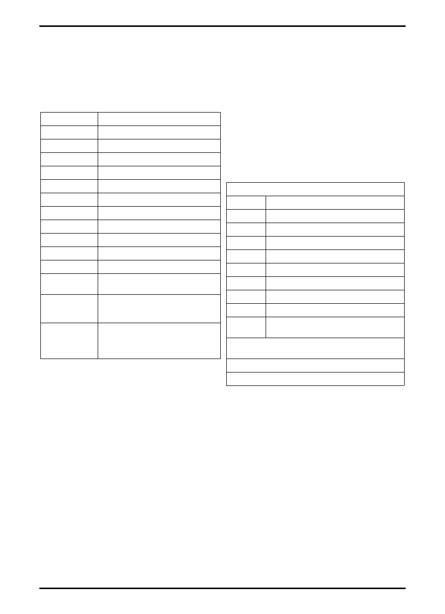
The following diagnostics can be displayed:

Control panel can be operated in all functions while

displaying active diagnostics. Operator is able to change

set point temperature, vent mode and blower fan speed.

To return system to normal operation, turn unit off and on

again.

ERROR CODE PROBLEM

E0

No faults detected

E1

Cab sensor shorted

E2

Cab sensor disconnected

E3

Evaporator probe shorted

E4

Evaporator probe disconnected

E5

Outlet duct sensor shorted

E6

Outlet duct sensor disconnected

E7

Ambient sensor shorted

E8

Ambient sensor disconnected

E9

Water valve shorted

E10

Water valve disconnected

E13

Water valve failed, stuck or not 

responding*

E14

Mode door stuck, actuator 

disconnected, failed or not 

responding*

E17

ECU module underpowerd, failed, 

or disconnected or serial 

communication wires disconnected 

or damaged.

Definition of DISPLAY

Display

Definition

CAB

Cab Airflow Temperature

DUCT

Air in Duct Temperature 

EUAP

Evaporator Core Temperature 

A-C

Compressor Clutch (On/Off)

HEAT

Water Valve Position (0-100%t open)

PRES

Pressure Cut Out Switch (On/Off)*

SUN

Sunlight Value (0-100)**

FAN

Blower Fan Duty Cycle (0-100)***

DOOR

Mode Door Actuator Feedback Position 

(0-100% of travel)

* Off position is caused by exceeding pressure limit 

7 PSI.

** 100 is maximum value

*** 100 is maximum speed

5-38

627333-A  

HVAC Testing and Adjusting

Troubleshooting Using Active 
Diagnostics

Several systems can be checked with active

diagnostics.

Checking Temperature Sensors

Use following procedure to verify temperature sensor

readings:

CAB - Cab air temperature

DUCT - Duct air temperature

EUAP - Evaporator core temperature (Switch)

DOOR - Mode Door Actuator Feedback Position

1. Measure temperature near sensor being checked.

2. Enter active troubleshooting. Refer to Entering

Active Troubleshooting for instructions about active

troubleshooting.

3. CAB is first code displayed, continue to sensor

being verified. Displayed temperature should be

near reading of thermometer.

4. If temperatures are not similar, verify the following: 

Accuracy of thermometer.

Wiring connections for temperature sensors in

cab.

Check displayed temperature for other modes

to verify control module is not faulty.

If all temperature sensors display 

−54 degrees

C

  (−65 degrees F), replace HVAC control

module.

Check power to control module.

Check serial communications between control

panel and control module for damage.

Check for poor wire connections.

5. Probable Solutions

Repair faulty wire connections.

Replace temperature sensor and verify proper

operation.

Replace control module and verify proper

operation.

Checking Compressor Clutch

Use the following to verify operation of compressor

clutch:

NOTE: Test should be performed in air temperatures

greater than 21 degrees C (70 degrees F),

clutch may not engage below that temperature.

If necessary, use a heat source to warm outside

air temperature.

1. Move mode control switch to DEFROST.

2. Enter active troubleshooting. Refer to Entering

Active Troubleshooting for instructions on active

troubleshooting.

3. CAB is first code displayed. Continue to switch

being verified. Display should be A-C for

compressor clutch.

4. Compressor clutch should be engaged in defrost

mode and LED display should display ON. This

indicates compressor clutch is on.

NOTE: Test should be performed in air temperatures

greater than 21 degrees C (70 degrees F),

clutch may not engage below that temperature.

If necessary, use a heat source to warm outside

air temperature.

5. If LED display shows OFF verify the following:

Outside temperature is at least 21 degrees C

(70 degrees F).

Verify refrigerant charge present in A/C system.

Verify connections to refrigerant pressure

switches, refer to Checking Refrigerant

Pressure Switches for additional information.

Verify all wire connections.

6. If no other problems can be found and display

shows OFF, replace control module.

7. If LED shows ON, but clutch does not engage,

verify:

Check voltage supplied to compressor clutch.

Verify wire connection at compressor clutch.

Verify wire connection at relay in HVAC unit.

8. If display shows ON and compressor clutch is not

receiving 12 volts, replace control module.

9. If proper voltage is being supplied to compressor

clutch but compressor clutch does not engage,

replace compressor clutch.

627333-A  

5-39

HVAC Testing and Adjusting

Checking Refrigerant Pressure Switches

Use the following to verify operation of refrigerant

pressure switches:

NOTE: Test should be performed in air temperatures

greater than 21 degrees C (70 degrees F),

clutch may not engage below that

temperature. If necessary, use a heat source

to warm outside air temperature.

1. Turn rotary switch to Head-Foot position.

2. Set temperature control to maximum heat.

3. Enter active troubleshooting, refer to Entering

Active Troubleshooting for instructions on active

troubleshooting.

4. CAB is first code displayed, continue to switch

being verified. PRES for refrigerant pressure

switches will be displayed.

5. Display shows ON, indicating sufficient, but not

excessive pressure in system.

6. If display shows OFF, verify air conditioning system

has appropriate charge of refrigerant. SS 2.1 kg

(4.65 lb). MT800 2.3 kg (5 lb).

7. If refrigerant charge is correct, verify:

Inspect high and low pressure switches for

damage.

Verify wire connections.

Check wire harness for damage or poor

terminal connections.

8. If items in step 6 are correct, replace pressure

switches and check for normal information.

9. If system does not operate normally, replace

control module and check again for normal

operation.

5-40

627333-A  

HVAC Testing and Adjusting

Checking Actuator for Water Valve

Use the following to verify water valve actuator

operation:

1. Verify engine coolant system is full of coolant.

2. Turn switch to Head-Foot position.

3. Enter active troubleshooting, refer to Entering Active

Troubleshooting for instructions about active

troubleshooting.

4. CAB is first code displayed, continue to sensor

being verified. HEAT for check water valve actuator

will be displayed.

5. Engine coolant must be near operating temperature.

6. Set temperature control to maximum heat, display

should increase to 100. When a high number is

displayed, heated air should be felt from vents.

7. Set temperature control to maximum cooling.

Display should decrease to zero and air should

become cooler.

8. If displayed number does not change in steps 6 and

7 or if number does not reach 0 or 100, check the

following:

Inspect wire connections for water valve

actuator.

Check for damage on wire harness.

9. Replace water valve and check for normal

operation.

NOTE: If debris is found in the coolant system, flush

coolant system and determine source of debris.

10. If the problem continues, replace control module.

Checking Blower Fan

Verifying operation of blower fan:

NOTE: Problems with blower fan are normally obvious,

however, checking the output control of the

control module to blower motor may be

necessary.

1. Enter active troubleshooting, refer to Entering Active

Troubleshooting for instructions about active

troubleshooting.

2. CAB is first code displayed, continue to sensor

being verified. FAN will be displayed, check signal

being sent to fan from control module.

3. Display will show pulse width modulation sent to

blower motor. Value will range from 27-100. Vary

blower fan speed and verify pulse width modulation

changes.

NOTE: In AUTO mode, fan speed may not reach lowest

possible speed due to logic of control module.

4. If speed does not change, replace control panel.

Checking Mode Door Actuator

Use the following to verify mode door actuator operation:

1. Enter active troubleshooting, refer to Entering Active

Troubleshooting for instructions about active

troubleshooting.

2. CAB is first code displayed, continue to sensor

being verified. DOOR will be displayed, check signal

being sent to actuator from control module.

3. Value displayed will show current position of

actuator, from 0-100.

NOTE: Extremes of these values are not normally

reached as door stops prevent extreme

movements of actuator.

4. Use rotary switch to change position of actuator and

verify displayed value changes.

5. If displayed value does not change, inspect

following items:

Wire connections.

Check for wiring harness damage.

6. Replace actuator and check for normal operation.

7. If problem continues, replace control panel and

check for normal operation

8. If problem continues, replace control module and

check for normal operation.


Content   ..  109  110  111  112   ..