Challenger Terra Gator 3244 Chassis. Manual - part 33
627333-A
3-45
Disassembly and Assembly
12. Tipping over the cab untill the transmission can be
removed/installated.
m
WARNING: Make sure the cab does not
hit anything. Otherwise damage to the
cab will by result.
IMPORTANT: By tipping over the cab this far. The
center of gravity is in front of the rotating point
of the cab. So there is no support needed
underneath the cab.
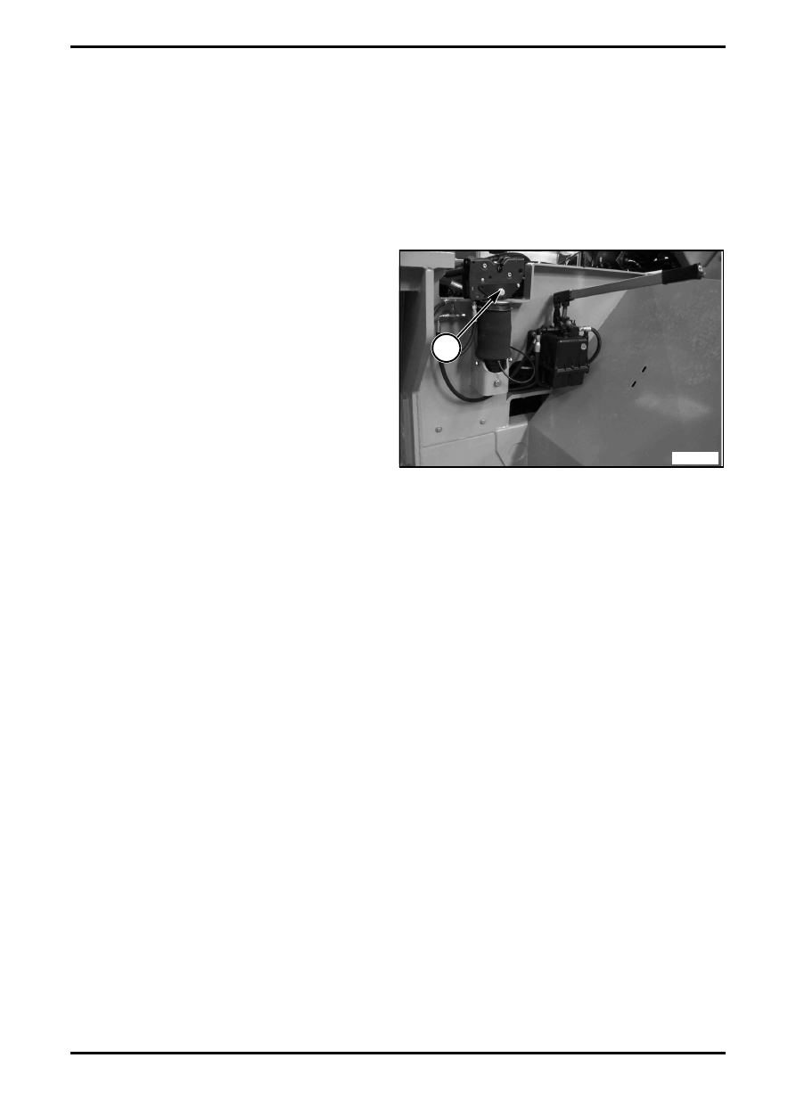
Lower the Cab
FIG. 5: Cab suspension and lock (4) at rear side of
cab.
To lower the cab act as follows:
1. Close the knob (1) on the handpump (CCW);
2. Place pump lever (2) in the pump and pump down
the cab.
m
WARNING: When the cab past the center
of gravity, the cab will come in a free fall.
When the cab is lower by its weight, close
the knob (1) on the handpump (CCW).
3. Lower or tipping over the cab so the locking pin can
be installed.
4. Install the wire rope (5) underneath the cab;
5. Remove the lock pin (3) from it’s locking position;
m
DANGER: Make sure there’s nobody
under the cab.
6. Open the knob (1) (CCW) to depressurize the
system. The cab will lower by its weight;
The rear suspesion will lock its self.
Leave the knob (1) in the “open” position.
7. Restore the lock pin with retainer in this locking
position underneath the cab;
8. Remove the pump lever (3) of the pump. Place the
pump lever back to the storage compartment.
9. Install the cooler supports above the engine;
10. Install the bonnet, frame and side panels.
FIG. 5
MIMG_4483
4