Challenger Terra Gator 3244 Chassis. Manual - part 28
 

  Index      Challenger     Challenger Terra Gator 3244 Chassis - service repair manual 2009 year


Search            


Content   ..  26  27  28  29   ..


Challenger Terra Gator 3244 Chassis. Manual - part 28


627333-A  

3-25

Testing and Adjusting

PRESSURE FOR TRANSMISSION 
LUBRICATION

FIG. 5:

m

WARNING: Escaping fluid under

pressure, even a pinhole size leak, can

penetrate body tissue, causing serious

injury, and possible death. If fluid is

injected into your skin, it must be treated

immediately by a doctor familiar with this

of injury.

Always use a board or cardboard when

checking for a leak.

m

WARNING: Personal injury can result

form hydraulic oil pressure and hot oil.

Hydraulic oil pressure can remain in the

hydraulic system after the engine has

been stopped. Serious injury can be

caused if this pressure is not released

before any service is done on the

hydraulic system.

Make sure all of the attachments have

been lowered, oil is cool before removing

any components or lines. Remove the oil

filler cap only when the engine is

stopped, and the filler cap is cool enough

to touch with your bare hand.

IMPORTANT: Care must be taken to ensure that fluids

are contained during performance of

inspection, maintenance, testing, adjusting

and repair of the product. Be prepared to

collect the fluid with suitable containers before

opening any compartment or disassembling

any component containing fluids.

Introduction

This test will show the following conditions of the

conditions exist:

Oil pressure to the transmission lubrication circuit is

good.

The transmission lubrication relief valve is closed.

Required Tools

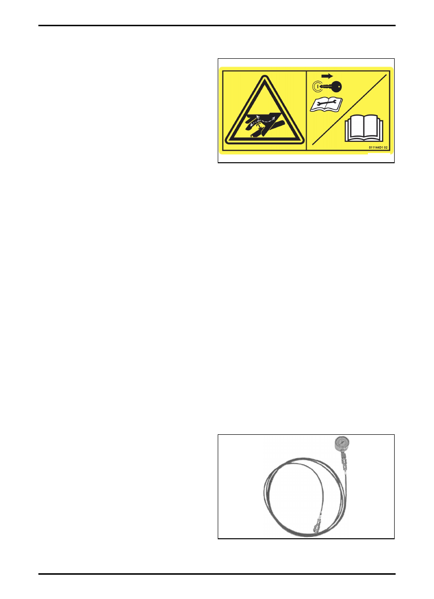
FIG. 6: The tool to check the oil pressure contains a:

Pressure Gauge, to read the pressure;

Fitting, to connect the pressure gauge to the hose;

Quick Connect Coupler, to connect the pressure

gauge to the transmission.

Hose, to allow make a distance between pressure

gauge and the measure point.

FIG. 5

Q000119S

FIG. 6

Q000046S

Testing and Adjusting

3-26

627333-A  

Test Procedure

FIG. 7: Pressure tap location for lubrication test.

Pressure gauges are used in the following test

procedure.

1. Attach a coupler to the transmission lubrication

pressure tap (1). If necessary, connect the

pressure hose. Install a pressure gauge 400 kPa

(58 psi) to the fitting.

2. Start the engine and warm the oil up to 60°C

(140°F).

3. Run the engine at LOW idle rpm with the

transmission control lever in the neutral position.

The pressure on the gauge must be a minimum of

4 kPa (0.5 psi).

4. Run the engine at HIGH idle rpm with the

transmission control lever in the neutral position.

The pressure on the gauge must be 179 ± 27 kPa

(26 ± 4 psi).

5. When the test is complete, stop the engine and

remove the test equipment.

FIG. 7

Q000049S

1

627333-A  

3-27

Testing and Adjusting

MODULATING VALVE

FIG. 8:

m

WARNING: Escaping fluid under

pressure, even a pinhole size leak, can

penetrate body tissue, causing serious

injury, and possible death. If fluid is

injected into your skin, it must be treated

immediately by a doctor familiar with this

of injury.

Always use a board or cardboard when

checking for a leak.

m

WARNING: Personal injury can result

form hydraulic oil pressure and hot oil.

Hydraulic oil pressure can remain in the

hydraulic system after the engine has

been stopped. Serious injury can be

caused if this pressure is not released

before any service is done on the

hydraulic system.

Make sure all of the attachments have

been lowered, oil is cool before removing

any components or lines. Remove the oil

filler cap only when the engine is

stopped, and the filler cap is cool enough

to touch with your bare hand.

IMPORTANT: Care must be taken to ensure that fluids

are contained during performance of

inspection, maintenance, testing, adjusting

and repair of the product. Be prepared to

collect the fluid with suitable containers before

opening any compartment or disassembling

any component containing fluids.

Introduction

The following test procedure will check the pressure of

the charge oil that is being delivered from a modulating

valve (transmission) to a transmission clutch. There are

niin individual modulating valves that control the nine

transmission cltuches. The modulating valves

(transmission) are modulated. The modulation of these

valves can be adjusted.

Required Tools

FIG. 9: The tool to check the oil pressure contains a:

Pressure Gauge, to read the pressure;

Fitting, to connect the pressure gauge to the hose;

Quick Connect Coupler, to connet the pressure

gauge to the transmission.

Hose, to allow make a distance between pressure

gauge and the measure point.

FIG. 8

Q000119S

FIG. 9

Q000046S

Testing and Adjusting

3-28

627333-A  

Test Procedure

FIG. 10: Transmission clutches

Pressure gauges are used in the following test

procedure.

The designated letters are used to correlate a

modulating valve to the corresponding transmission

clutch, as shown.

1. Input Shaft;

2. Intermediate Shaft;

3. Output Shaft;

4. Transfer Gear shaft;

5. Reverse Shaft.

a. Clutch pack;

b. Planetary Carrier;

c. Clutch pack;

d. Clutch pack;

e. Clutch pack;

f.

Clutch pack;

g. Planetary Carrier;

h. Clutch pack;

i.

Clutch pack.

FIG. 10

Q000044S

G

H

I

B

E

F

D

C

4

3

2

1

Q000062S

5

4

3

2

A

5


Content   ..  26  27  28  29   ..