HUAWEI OptiX OSN 8800 T64/T32 Intelligent Optical Transport Platform. Product Description - part 33
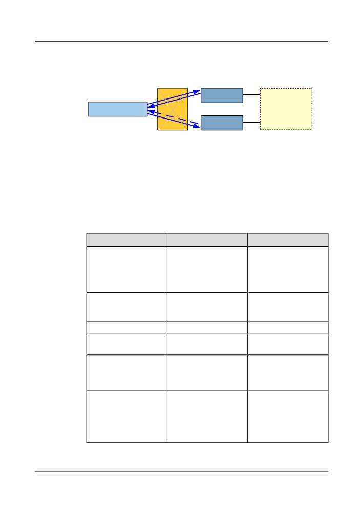
Figure 7-63 Model of the protection for electrical-layer ASON services
Electrical-Layer Diamond (ODUk SNCP Protection)
Line Unit
Tributary Unit
ROADM
Line Unit
7.7.2 Quick Finding of Optical-Layer and Electrical-Layer Functions
The functions of optical-layer and electrical-layer services implemented by the ASON software
are different.
The WDM ASON features support the optical-layer ASON function and the electrical-layer
ASON function, as described in Table 7-26.
Table 7-26 Optical-layer ASON and electrical-layer ASON
Item
Optical-Layer ASON
Electrical-Layer ASON
Control channel
D4-D12 bytes of the optical
RES or SM_TTI and
supervisory channel (OSC)
PM_TTI bytes of the OTN
in outband manner.
overhead.
The system uses RES bytes
by default.
Supported service type
Services of OCh wavelength
Services of ODUk
level .
wavelength level (k=0, 1, 2,
3).
Supported SLA
Silver and copper.
Diamond, silver, and copper.
Hardware configuration
FIU board, SC1/2 board, and
Cross-connect boards and
requirements
WSS board.
relevant tributary boards.
Rerouting trigger conditions
Optical-layer SF alarm. For
Electrical-layer SF and SD
detailed information refer to
alarms. For detailed
Rerouting of an LSP.
information refer to
Rerouting of an LSP.
Rerouting mechanism
After a service is interrupted,
After a service is interrupted,
rerouting is initiated on the
a new service is created
source node, and a new trail
through cross-connections
is created through ROADM
on the centralized cross-
cross-connections.
connect board or tributary
board.
345

Item
Optical-Layer ASON
Electrical-Layer ASON
Special technology
Wavelength tunable
NA
rerouting, which solves the
wavelength blocking
problem in rerouting.
Table 7-27 lists the functions of optical-layer ASON services of different SLAs.
Table 7-27 Functions of optical-layer ASON services of different SLAs
Item
Silver Service
Copper Service
Protection and restoration
Restoration
No protection
policy
No restoration
Technologies for
Rerouting
-
implementation
Technical implementation
Real-time computation
-
without presetting protection
channels
Bandwidth utilization
High
Excessively high
Supported
Route pre-
Supported
Supported
functions
computation
Route
Supported
Supported
optimization
and service
reversion
Conversion
Supported
Supported
between
traditional and
ASON services
Switching
-
-
between
services of
different SLAs
Pre-set
Supported
-
restoration trail
Service
Supported
Supported
association
Wavelength
Supported
-
tunable
rerouting
346

Item
Silver Service
Copper Service
Optical
Supported
Supported
parameters
Table 7-28 lists the functions of electrical-layer ASON services of different SLAs.
Table 7-28 Functions of electrical-layer ASON services of different SLAs
Item
Diamond Service
Silver Service
Copper Service
Protection and
Protection and
Restoration
No protection
restoration policy
restoration
No restoration
Technologies for
ODUk SNCP and
Rerouting
-
implementation
rerouting
Technical
Protection always
Real-time
-
implementation
provided when the
computation without
network bandwidth
presetting protection
is available
channels
Bandwidth utilization
Low
High
Excessively high
Support
Routing
Supported
Supported
Supported
ed
pre-
function
computatio
s
n
Route
Supported
Supported
-
optimizatio
n and
service
reversion
Conversio
Supported
Supported
Supported
n between
traditional
and ASON
services
Switching
Supported
Supported
Supported
between
services of
different
SLAs
Pre-set
Supported
Supported
-
restoration
trail
Service
-
Supported
Supported
association
347

Item
Diamond Service
Silver Service
Copper Service
Wavelengt
-
-
-
h tunable
rerouting
Optical
-
-
-
parameters
7.7.3 Prerequisites for Enabling ASON Features
Certain hardware and software prerequisites must be available when the optical-layer and
electrical-layer ASON features are enabled.
The prerequisites for enabling the optical-layer ASON features are as follows:
l The OSC board must be configured.
l The FIU board must be configured.
l The WSS board must be configured.
l It is required to configure two SCC boards in the master subrack.
The prerequisites for enabling the electrical-layer ASON features are as follows:
l The centralized cross-connect board must be configured.
l It is required to configure two SCC boards in the master subrack.
The software prerequisites for enabling ASON features are as follows:
l The NE software version must support the ASON features. Contact Huawei engineers to
determine whether the current NE software version supports the ASON features.
l The version of the mapping NMS that is delivered must support the ASON features.
l The ASON features are controlled by the license on the NMS. The ASON features can be
enabled for only users who apply for and purchase this license or obtain a special permission
from Huawei.
NOTE
There are two types of license: the license for basic ASON features and the license for enabling services.
The first type of license is used to control the ASON features of a single station. The second type of license
is specific for the services on the entire network and is used to control the number of services of different
rates on an ASON network.
NOTE
l 2.5G and 5G boards do not support optical-layer ASON services.
l Individual tributary boards do not support optical-layer ASON services on their client sides.
7.7.4 Conditions for Configuring ASON Services
Certain configuration conditions must be met to ensure successful creation of the optical-layer
and electrical-layer ASON services.
NOTE
The optical power of each channel of an ASON NE must be controlled by the software, and thus an EVOA
must be configured inside the ASON NE.
348
Configuring Electrical-Layer ASON Services
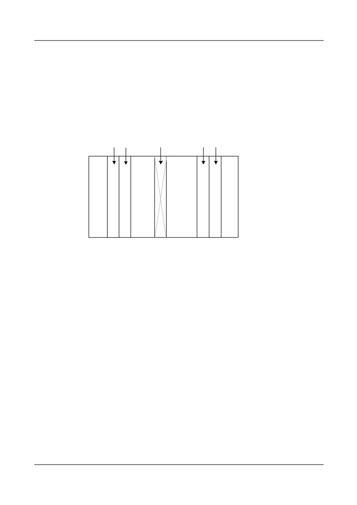
In the case of electrical-layer ASON services, a centralized cross-connect board must be used
to groom sub-wavelength services. In the case of a site where the main and slave subracks are
configured, electrical-layer cross-connections cannot be groomed between subracks (between
the master and slave subracks and between slave subracks). Hence, the working trail and
protection trail (or restoration trail) of the electrical-layer services must be led out from the site
through the same subrack. See Figure 7-64.
Figure 7-64 Configuring electrical-layer ASON services
Tributary
Working
Cross-Connect
Protection
Retrieve
board
board
board
board
board
T
N
N
N
Q
S
S
S
X
2
2
2
Configuring Optical-Layer ASON Services
The process of configuring the optical-layer ASON services is more complex than the process
of configuring the electrical-layer ASON services.
The optical-layer ASON services are dynamic, and their restoration routes are not fixed.
Therefore, the reconfigurable optical add/drop multiplexer (ROADM) board should be
configured.
l One pair of WSS boards should be configured for each dimension.
l In the case of silver services, one pair of WSS boards should be configured at each
wavelength add/drop node.
l In the case of permanent 1+1 diamond service and rerouting 1+1 diamond service, two
pairs of WSS boards should be configured at each wavelength add/drop node (one pair is
for the working channel, and the other pair is for the protection channel).
The ASON protocol is embedded in the OSC overheads. Hence, the OSC board must be
configured.
Figure 7-65, which is the diagram for configuring the optical-layer ASON services, shows the
number of WSS boards required by the sliver services. If the services are diamond services with
the rerouting function, a pair of WSS boards (a pair of working boards and a pair of protection
boards) must be configured at points where the services are added and dropped.
349
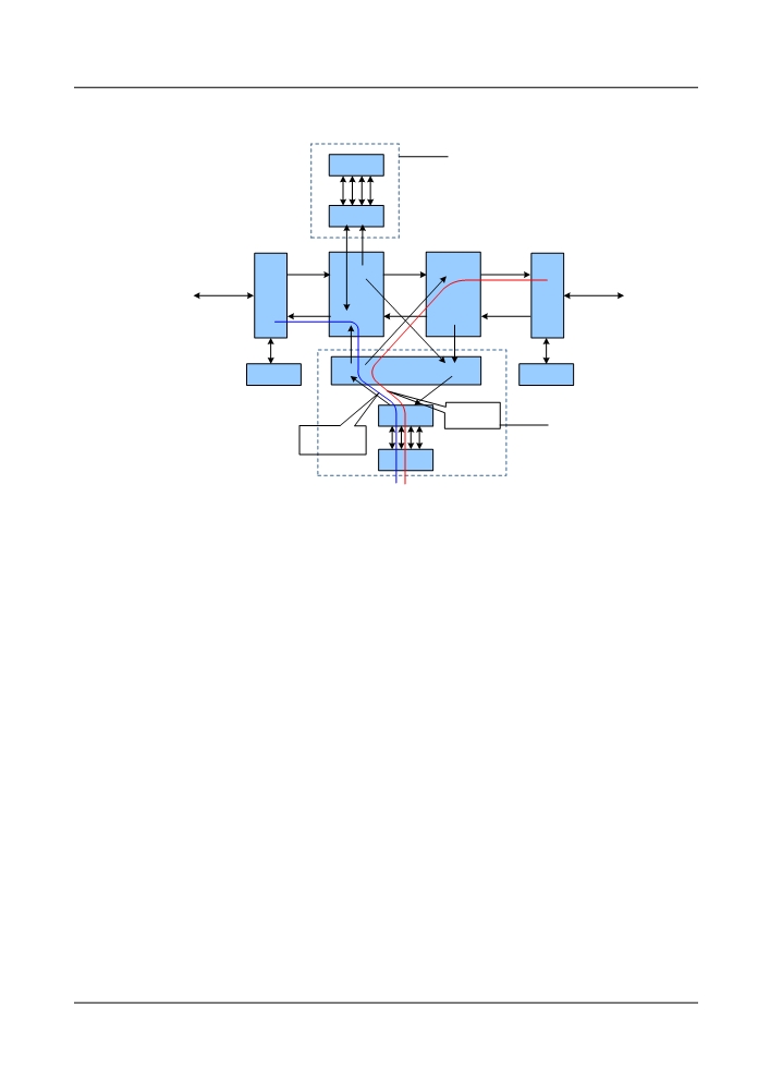
Figure 7-65 Configuring optical-layer ASON services
Does not
support
OTU
reroute
MR4
WSD9
RMU9
W
E
FIU
FIU
RMU9
WSD9
WSD9
RMU9
OSC
OSC
Protection
MR4
Support
trail
Working
reroute
trail
OTU
350
8
Operation, Administration, and
Maintenance
About This Chapter
8.1 Automatic Deployment Commissioning
The system supports automatic deployment commissioning. This automatic deployment
commissioning function implements automatic commissioning of a new network, optical power
commissioning of an expanded network or in the case of rerouting, real-time optimization of
network performance, and fiber connection test. In the deployment phase, the automatic
deployment commissioning function can be used to adjust the optical power for the main optical
paths and implement performance adjustment for the entire network. This can solve the
performance degradation problem caused by wavelength grooming, aged optical paths, or
artificial factors in the maintenance phase.
8.2 End-to-End Service Configuration
The system provides end-to-end OTN service configurations management function, which helps
simplify the configuration process. This function helps shorten the network deployment time
and implement automatic management of a network.
8.3 Supervision and Administration Module
The system control and communication (SCC) board monitors and manages the system NE.
8.4 Communication and Maintenance Interfaces
The system provides abundant interfaces for data communication and equipment maintenance.
8.5 Orderwire Function
The orderwire provides voice communication for the operation engineers or maintenance
engineers at different stations.
8.6 Security Management
The NMS uses many schemes to manage the security of the OptiX OSN 8800/6800/3800 NE.
8.7 Master-Slave Subrack Management
The OptiX OSN 8800 supports master-slave subrack management. When multiple subracks are
required on one NE, the master-slave subrack mode should be used for unified management of
these subracks. In this manner, the IP resources can be saved. In addition, when optical-layer
ASON and optical-layer services are configured on the NE, the optical subracks on the NE should
351
be taken out to form a new NE for management. This facilitates the maintenance and reduces
the management cost.
8.8 Administration and Maintenance
The design of the cabinet and boards and the configuration of the system incorporate the
requirements with easy and effective operation, administration, and maintenance of the
equipment.
352
8.1 Automatic Deployment Commissioning
The system supports automatic deployment commissioning. This automatic deployment
commissioning function implements automatic commissioning of a new network, optical power
commissioning of an expanded network or in the case of rerouting, real-time optimization of
network performance, and fiber connection test. In the deployment phase, the automatic
deployment commissioning function can be used to adjust the optical power for the main optical
paths and implement performance adjustment for the entire network. This can solve the
performance degradation problem caused by wavelength grooming, aged optical paths, or
artificial factors in the maintenance phase.
This automatic deployment commissioning implements the function as follows:
l Supports fiber connection tests.
l Supports automatic commissioning of a new network, including commissioning of main
optical paths and adjusting of channel flatness.
l Supports optical power commissioning in a scenario in which a site is expanded or
wavelengths are added or removed.
l Supports commissioning of an ASON network, including pre-commissioning of planned
trails and optimization of the optical power after rerouting occurs.
l Supports optimization of O&M performance of a network, including the control of optical
spectral flatness when the wavelength optical power on a channel fluctuates and
optimization commissioning based on service performance.
l Provides detailed information in a report which provides detailed information about boards,
optical power, and BER on the basis of a network or link. This facilitates the maintenance
personnel to understand the running conditions of the network running.
8.2 End-to-End Service Configuration
The system provides end-to-end OTN service configurations management function, which helps
simplify the configuration process. This function helps shorten the network deployment time
and implement automatic management of a network.
When configuring an end-to-end OTN service, you can create a service trail that traverses
different layers and directly create a client service trail. You do not need to know how the service
grooming between the OTN layers is implemented or create an ODU0/ODU1/ODU2/ODU3
server trail at each layer. After you create a client service, the client service trails at different
OTN layers are generated automatically. This simplifies the service configuration process.
The end-to-end OTN service configuration includes creating, querying, deleting, and modifying
an end-to-end service and optimizing an end-to-end service. The latter is also known as service
defragmentation.
8.3 Supervision and Administration Module
The system control and communication (SCC) board monitors and manages the system NE.
The SCC board collects the state information, alarm events, and performance parameters from
the functional modules of each board.
353

Then, the SCC converts, processes, and stores the information and parameters. At the same time,
it sends the control and administration information to the other functional modules.
The SCC provides functional interfaces to facilitate the communication between the functional
modules of each board and the NM, as shown in Table 8-1.
Table 8-1 Description of the functional interfaces of the SCC
Functional
Description
Interface
F&fa
Connect the RS-232 interface to a PC or a workstation for
commissioning.
Etherneta
TMN interface, local NE management interface, and internal
communication interface, used for commissioning
OAMa
The operation, administration, and maintenance interface.
The X.25 interface is provided to communicate with the terminal
through the public packet switched network.
DCC communication
Provides the data communication channel (DCC) of the supervisory
link.
Communication
Communicates with other boards, collects performance data, and
module
delivers the configuration.
Qx
Network management communication interface.
a: The interface functions of the SCC have corresponding external physical interfaces in the
subrack interface area on the EFI1 and EFI2. For details, see the Hardware Description.
The SCC monitors the running status of the boards on the NE.
The main monitoring parameters include:
l Input optical power
l Output optical power
l Laser temperature
l B1 performance parameter
l FEC performance parameter
8.4 Communication and Maintenance Interfaces
The system provides abundant interfaces for data communication and equipment maintenance.
The EFI1, EFI2, STI and ATE boards implement functions, such as clock signal input and output,
alarm input, alarm output, and alarm cascading, to monitor the remote external systems. Table
8-2 shows the interface functions of the STI, EFI, and ATE.
The AUX board provides the inter-board and inter-subrack communication. The AUX board
does not provide external interfaces but only four indicators.
354
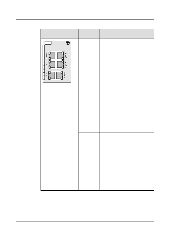
Table 8-2 Interface function of STI, EFI, and ATE
Front Panel Appearance
Panel
Interface
Usage
Interface
Type
ALMO1
RJ-45
The definitions for the pins of
ATE
the ALM01 and ALM02
ALMO2
interfaces are the same. The
ALMO3
two interfaces are used for
ALMO4
output and cascading,
respectively. The definitions
for the pins of the ALM03
and ALM04 interfaces are the
same. The two interfaces are
used for output and
cascading, respectively.
Alarm outputs are sent to the
DC power distribution
cabinet through the output
interface and the cascading
interface. You can configure
it to be the other outputs to
realize integrated display of
alarms. The OptiX OSN 8800
provides eight alarm outputs.
Defaults of the first three are
critical alarm, major alarm,
and minor alarm. The other
five are reserved. Alarm
outputs can be cascaded.
ALMI1
RJ-45
External alarm signal input
function is designed for
ALMI2
requirements when the alarm
signals of the external
systems (such as the
environment monitory) need
remote monitoring.
The OptiX OSN 8800
provides eight alarm inputs.
The name of the eight alarms
can be configured to
cooperate with the external
system to realize remote
monitoring of external
alarms.
355