OptiX OSN 7500 Intelligent Optical Switching System. Technical Manual - part 6
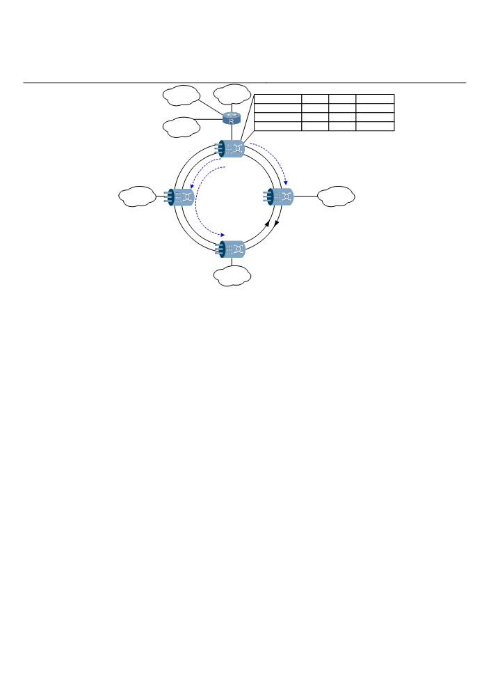
VLAN 3
Traffic
Tunnel
VC
Destination
Port1+VLAN 2
200
200
Node 2
Port1+VLAN 3
300
300
Node 3
VLAN 4
Port1+VLAN 4
400
400
Node 4
GE
Node 1
FE
FE
VLAN 2
Node 2
Node 4
VLAN 4
Dual-ring
2.5 Gbit/s RPR
Node 3
FE
VLAN 3
Figure 6-14 EVPL service convergence
2. EVPLAN
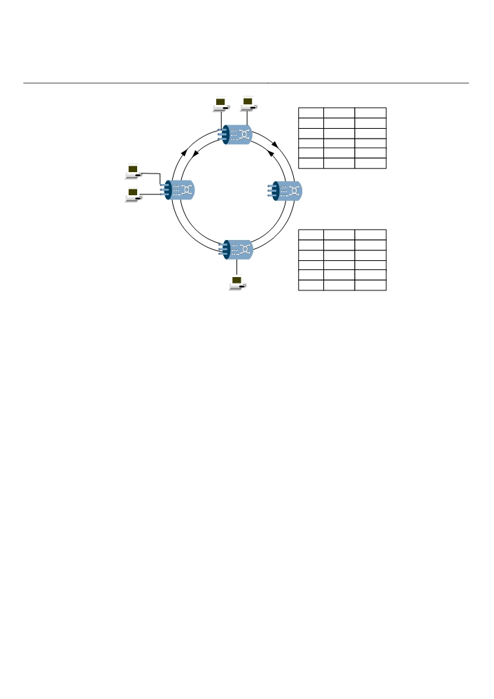
The EVPLAN service supports traffic classification based on port or port + VLAN, and
encapsulates and forwards the traffic in the form of MPLS VMAN. The EVPLAN
service is realized by creating virtual bridge (VB) in the board. Each board may have
up to 32 VBs, each of which has 16 logic ports. VB supports source MAC address
learning and static MAC route configuration. Figure 6-15 shows an example of
EVPLAN service. The VB of each node determines the forward port of packets
through address learning, rpr1 is the port to access packets to the RPR. For node 1, if
the destination address is A1, the packet is forwarded through port 1; if the destination
is A2, the packet is forwarded through port 2. If the destination is B1, B2 or C1, the
packet is forwarded through port rpr1 to the RPR, added with a VMAN label being 100.
Node 2 forwards packets in the same way.
6-16
A2
MAC forwarding table of node 1
MAC
Port
VMAN
Port 1
Port 2
A1
port 1
none
A2
port 2
none
B1
rpr1
100
Node 1
B2
rpr1
100
B1
C1
rpr1
100
Dual-ring
2.5 Gbit/s RPR
Port 1
Node 2
Node 4
Port 2
B2
MAC forwarding table of node 2
Node 3
MAC
Port
VMAN
A1
rpr1
100
A2
rpr1
100
Port 1
B1
port 1
none
B2
port 2
none
C1
C1
rpr1
100
Figure 6-15 EVPLAN service
6.2.3 Protection
The RPR service of the OptiX OSN equipment takes the protection of several levels,
including:
Wrapping and Steering
Spanning tree and LCAS
Protection of optical transmission layer, such as MSP and SNCP
1. Wrapping
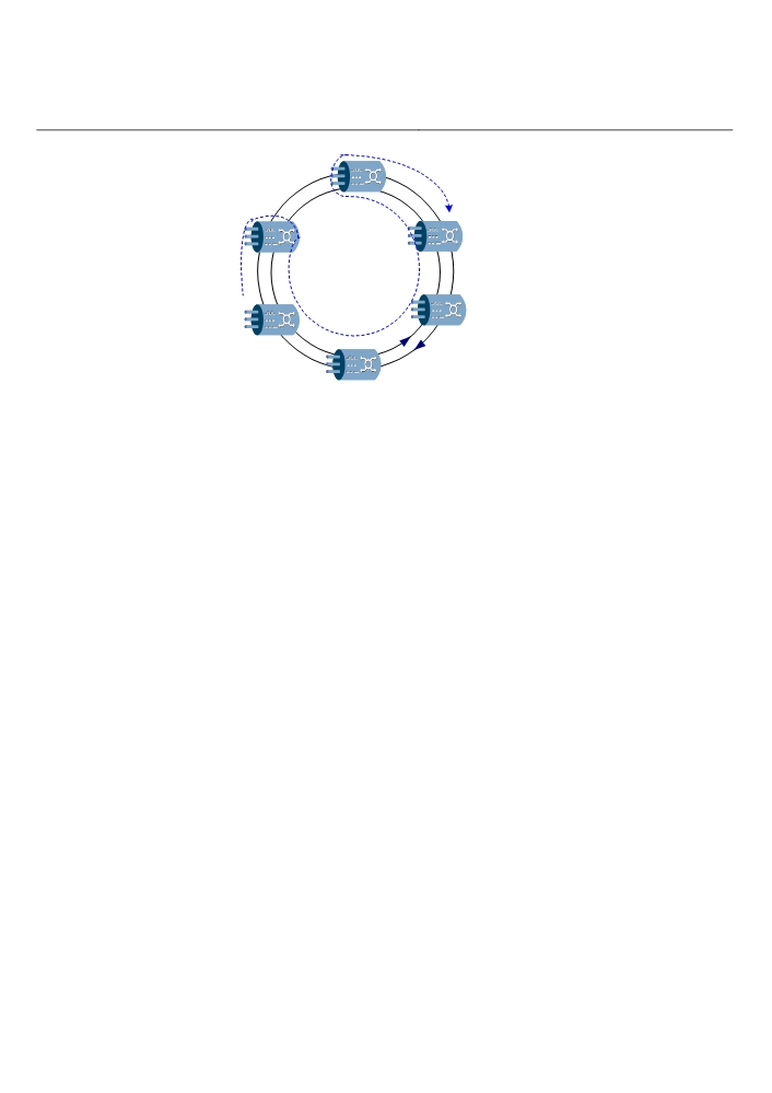
If an equipment or facility failure is detected, the traffic is wrapped back to the opposite
direction at the stations adjacent to the failure, connecting the outer ring with the inner
ring. The protection switching time is less than 50ms. Though featuring fast protection
switching, wrapping protection wastes bandwidth. As illustrated in Figure 6-16, traffic
is transferred from node 4 to node 1 through nodes 3 and 2. If there is a fiber cut
between node 2 and node 3, they will wrap the traffic and connect the two rings
together for protection.
6-17
Fiber cut
Traffic flow
X
Node 3
Node 1
Dual-ring
2.5 Gbit/s RPR
Node 6
Node 4
Node 5
Figure 6-16 Wrapping protection
2. Steering
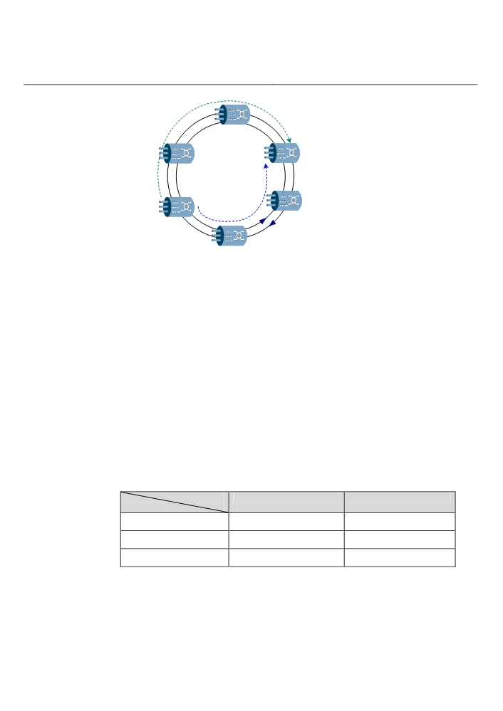
For steering protection, a station shall not wrap a failed segment when a failure is
detected. Instead, the source node will send traffic to the destination through a route
avoiding the failed link. The protection switching time is less than 50ms. The steering
protection does not waste bandwidth, however, it needs longer switching time and
some data before setting up a route may be lost. Figure 6-17 illustrates an example of
steering protection. Node 4 sends traffic to node 1 on the outer ring through nodes 3
and 2. If there is a fiber cut between node 2 and node 3, the topology discovery
function can help the traffic be transferred to node 1 over the inner ring through nodes
5 and 6.
6-18
Fiber cut
Traffic flow before
switching
X
Dual-ring
Node 3
Node 1
2.5 Gbit/s RPR
Traffic flow
Node 6
Node 4
after switching
Node 5
Figure 6-17 Steering protection
3. Spanning Tree and LCAS
For details about spanning tree and LCAS, refer to “6.1 Ethernet”.
6.3 ATM Features
This section describes the ATM features of the OptiX OSN 7500 in terms of
functionality, application, and protection.
6.3.1 Functions
The OptiX OSN 7500 provides four different ATM processing boards: ADL4, ADQ1,
IDL4 and IDQ1. The IDL4 and the IDQ1 support inverse multiplexing for ATM (IMA).
An ADL4/IDL4 board can access and process one STM-4 ATM service and an
ADQ1/IDQ1 board can access and process four STM-1 ATM services. When working
with the PL3/PD3 board, the ADL4 board or ADQ1 board can access and process E3
ATM services. The functions of the four boards are listed in Table 6-4.
Table 6-4 Functions of the four ATM boards
Board
ADL4/IDL4
ADQ1/IDQ1
Function
Front panel interface
1 x STM-4
4 x STM-1
Optical interface index
S-4.1, L-4.1
I-1, S-1.1, L-1.1
Optical interface type
Hot swappable LC (SFP)
Hot swappable LC (SFP)
6-19

ADL4/IDL4
ADQ1/IDQ1
Function
E3 ATM interface
Access 12 x E3 services
Access 12 x E3 services
through the PD3/PL3 board
through the PD3/PL3 board
Maximum uplink
8 VC4s, or 12 VC3s + 4
8 VC4s, 12 VC3s + 4 VC4s
bandwidth
VC4s
ATM switching capability
1.25 Gbit/s
1.25 Gbit/s
Mapping mode
VC3, VC4, VC4-4c, or
VC3, VC4, VC4-4c,
VC4-Xv (X=1 - 4)
VC4-Xv (X=1 - 4)
Processable service types
CBR, rt-VBR, nrt-VBR and
CBR, rt-VBR, nrt-VBR and
UBR
UBR
Number of ATM
8000
8000
connections
Traffic type and QoS
IETF RFC2514
IETF RFC2514
Supportable ATM
Spatial multicast and logic
Spatial multicast and logic
multicast connections
multicast
multicast
ATM protection (ITU-T
Unidirectional/bidirectional
Unidirectional/bidirectional
I.630)
1+1/1:1 VPRing or VCRing
1+1/1:1 VPRing or VCRing
OAM function (ITU-T
AIS, RDI, LB (Loopback),
AIS, RDI, LB, CC
I.610)
CC (continuity check)
6-20

1. Supportable Services and Traffic Types
The OptiX OSN 7500 supports CBR, rt-VBR, nrt-VBR, and UBR services rather than
ABR services. CBR services apply to voice services, as well as video services and
circuit simulation services of a constant bit rate. These services require guaranteed
transmission bandwidth and latency. Rt-VBR services apply to audio and video
services of a variable bit rate. Nrt-VBR services are mainly used for data transmission.
UBR services are generally used for LAN simulation and file transmission. In terms of
the supported service and traffic types, the OptiX OSN 7500 meets IETF RFC2514,
ATM Forum TM 4.0 and ATM Forum UNI 3.1 recommendations, as shown in the Table
6-5..
Table 6-5 Supportable ATM service and traffic types of the OptiX OSN 7500
No.
Traffic type
Service type
Parameter
1
atmNoTrafficDescriptor
UBR
None
2
atmNoClpNoScr
UBR.1
Clp01Pcr
CBR
Clp01Pcr
3
atmClpNoTaggingNoScr
CBR
Clp01Pcr, Clp0Pcr
4
atmClpTaggingNoScr
CBR
Clp01Pcr, Clp0Pcr
5
atmNoClpScr
nrt-VBR.1
Clp01Pcr, Clp01Scr, Mbs
6
atmClpNoTaggingScr
nrt-VBR.2
Clp01Pcr, Clp0Scr, Mbs
7
atmClpTaggingScr
nrt-VBR.3
Clp01Pcr, Clp0Scr, Mbs
8
atmClpNoTaggingMcr
ABR
Clp01Pcr, Cdvt, Mcr
9
atmClpTransparentNoScr
CBR.1
Clp01Pcr, Cdvt
10
atmClpTransparentScr
rt-VBR.1
Clp01Pcr, Clp01Scr, Mbs,
Cdvt
11
atmNoClpTaggingNoScr
UBR.2
Clp01Pcr, Cdvt
12
atmNoClpNoScrCdvt
UBR
Clp01Pcr, Cdvt
CBR
Clp01Pcr, Cdvt
13
atmNoClpScrCdvt
rt-VBR.1
Clp01Pcr, Clp01Scr, Mbs,
Cdvt
14
atmClpNoTaggingScrCdvt
rt-VBR.2
Clp01Pcr, Clp0Scr, Mbs, Cdvt
15
atmClpTaggingScrCdvt
rt-VBR.3
Clp01Pcr, Clp0Scr, Mbs, Cdvt
6-21
2. Application of Band Exclusive ATM Services
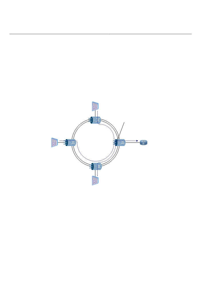
When the bandwidth is not shared, ATM services at the source and sink NEs are only
processed at the ATM layer through the ATM service process board. On intermediate
NEs, only SDH timeslot pass-through is performed, without ATM layer processing. In
this case, each ATM service has the whole VC3/VC4 channel to itself. The ATM
services are converged at the central node and then multiplexed to an STM-1 or
STM-4 optical port for output. As shown in the Figure 6-18, the 34 Mbit/s ATM services
of NE1 and NE3 each occupy a VC3 bandwidth. The 155 Mbit/s ATM service of NE2
occupies a VC4 bandwidth alone. SDH timeslot pass-through is only performed at
NE3. After they reach the central site NE4, they are converged through the ATM board
and output through the 622 Mbit/s optical interface.
DSLAM
34M ATM
Traffic
Service
Convergence
NE 1
155M ATM
2.5 Gbit/s SDH
622M ATM
Traffic
Ring
Traffic
NE 2
NE 4
Router
DSLAM
NE 3
34M ATM
Traffic
DSLAM
Figure 6-18 Application of Band exclusive ATM Services
3. Application of Band-Shared ATM Services
In shared rings VR-Ring and VC-Ring, the ATM services share the same bandwidth
and are multiplexed statistically. The ATM services on each NE share the same VC
(VC3, VC4, or VC-Xv) and are all processed on ATM layer. As shown in the Figure
6-19, NE1 accesses E3 ATM traffic through the tributary board and sends it to the ATM
board for ATM switching and protection (1+1/1:1) configuration. Then the traffic is
encapsulated into VC4-Xv and sent to the line through the cross-connect board. NE2
6-22
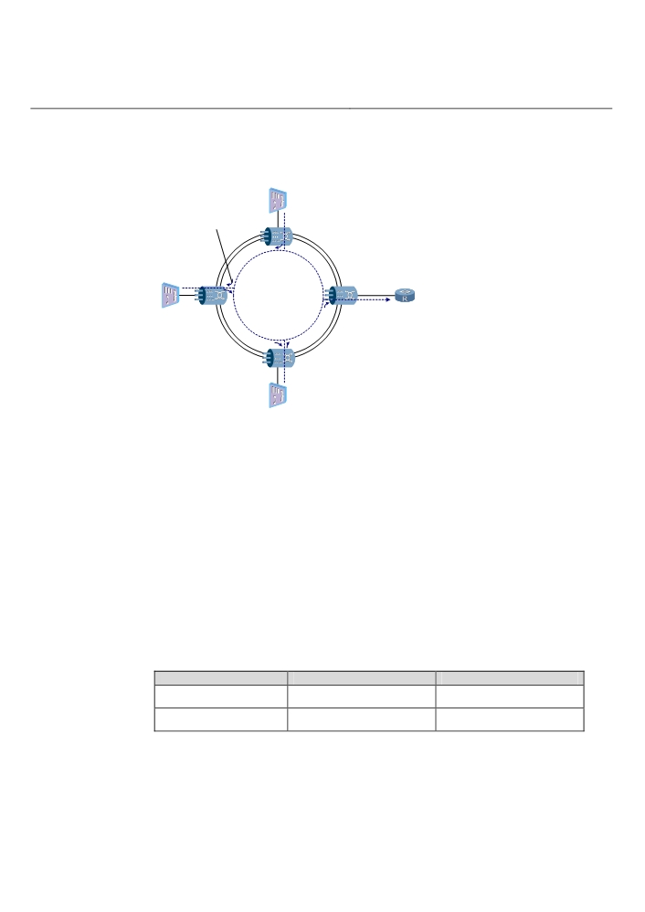
switching and protection configuration. The ATM traffic from NE1 is also dropped at
NE2 for ATM layer processing. Then the locally accessed traffic and that from NE1 are
encapsulated into the same VC4-Xv and sent to the next NE. The same goes at NE3
and NE4. A single VP/VC-Ring can have a maximum bandwidth of 300 Mbit/s.
The ATM traffic from NE1
DSLAM
is droped to the NE2, then
send to VP/VC-Ring after
34M ATM
converged with local
Traffic
NE 1
service.
155M ATM
Traffic
NE 4
Router
VC4-Xv
VP/VC-Ring
622M ATM
DSLAM
NE 2
Traffic
NE 3
34M ATM
Traffic
DSLAM
Figure 6-19 VP/VC-Ring
6.3.3 Protection
The ATM service of the OptiX OSN equipment is protected on many layers, including:
Protection on the ATM layer
Protection on the optical transmission layer, such as MSP, and SNCP.
1. Protection on the ATM Layer
Compliant with ITU-T Recommendation I.630, protection on the ATM layer can be
classified into many types according to different classification method, as shown in the
Table 6-6. You can select the configuration as required, for example, 1+1 bidirectional
non-revertive protection”.
Table 6-6 Classification of ATM protection
Classification mode
1+1 protection
1:1 protection
Switching direction
Unidirectional protection
Bidirectional protection
Connection level
VPC protection
VCC protection
6-23
1+1 protection
1:1 protection
Protection domain
Trail protection
Subnetwork connection
protection
Revertiblility
Revertive protection
Non-revertive protection
Protected object
Single connection protecton
Group connection protection
2. Protection on the Optical Transmission Layer
The ATM service is also protected by the self-healing network on the optical
transmission layer, such as MSP and SNCP. You can set the hold-off time for ATM
protection switching. When network impairment occurs, the MSP or SNCP on lower
layers can be switched first, thus achieving the protection of working ATM service (in
this case, the protection switching on the ATM layer will not be activated).
6-24
aturesOSN 7500
Technical Manual - System Description
7 Intelligent Features
7
Intelligent Features
The intelligent optical network integrates automatic switching and transmission. The
user end originates the service request dynamically, selects a route automatically, and
creates/cancels service connection through the control of signaling. This chapter
introduces the intelligent features and application of the OptiX OSN 7500.
Note:
The intelligent software system is to be purchased and installed additionally for the
OptiX OSN 7500.
The OptiX OSN 7500 provides a set of stand-alone intelligent software system that is
quite convenient and flexible in use in dynamic bandwidth allocation, intelligent route
finding and configuration of services. The bandwidth availability using the OptiX OSN
7500 is improved.
The OptiX OSN 7500:
Supports service level agreement (SLA).
Supports automatically configure the end-to-end service.
Supports mesh networking.
Provides traffic engineering control to guarantee the load-balance traffic network
wide and improve the bandwidth availability.
Provides distributed mesh network protections through real-time rerouting or a
7-1

aturesOSN 7500
Technical Manual - System Description
7 Intelligent Features
preconfigured route; support span protection and end-to-end service protection,
improving the scalability of the network.
7.1 SLA Service
1. Classification of SLA Service
The SLA service can be classified into multiple levels in terms of protection (high level
service, medium level service, reroute service, unprotected service and extra service,
and so on). Charges vary with the service levels and thus demands of different users
can be satisfied flexibly. The principle for classifying services is as follows:
High level service: Provided with 1+1 protection or alike, with the switch-ing time of
0-50ms.
Medium level service: Provided with M:N protection or alike (for example, two-fiber
MSP), with the switching time of 0-50ms.
Reroute service: Recalculate the path in real time, with the switching time from
100ms to several seconds.
Unprotected service: Provided with no protection in the case of any fault.
Extra service: Pre-empted by services with higher priorities when the network
resource is insufficient.
2. SLA-Based Protection at Different Service Levels
With the SLA service provided, the OptiX OSN 7500 enables the operators to win
more customers in a differentiated market with better service and lower cost.
Table 7-1 Differential protection for service at different levels
Service level
Protection level
Service quality
Diamond
High level protection
The QoS increases higher from
bottom up
Gold
Medium level protection
Silver
Rerouting protection
Copper
Non-protection
Iron
Preemptive
Diamond level service is to meet demands of users such as banks, securities,
important government offices, and so on. Gold level service is to satisfy the demands
for speech, multimedia and video. Silver level service is applicable to common data
service transmission. Services of copper and iron levels are suitable for applications
such as family network access
7-2