Huawei OptiX BWS 1600G. Technical Description - part 8
3 System Configuration
3.4 REG
3.4.1 Signal Flow
We have already discussed that the OLA can extend the optical transmission
distance without regeneration. However, when the distance is longer, such factors
as dispersion, optical noise, non-linear effect, or PMD will affect the transmission
performance. In this case, we need to regenerate the original signals. An REG
implements the 3R function, that is, reshaping, re-timing and regenerating, to
improve the signal quality and extend the transmission distance.
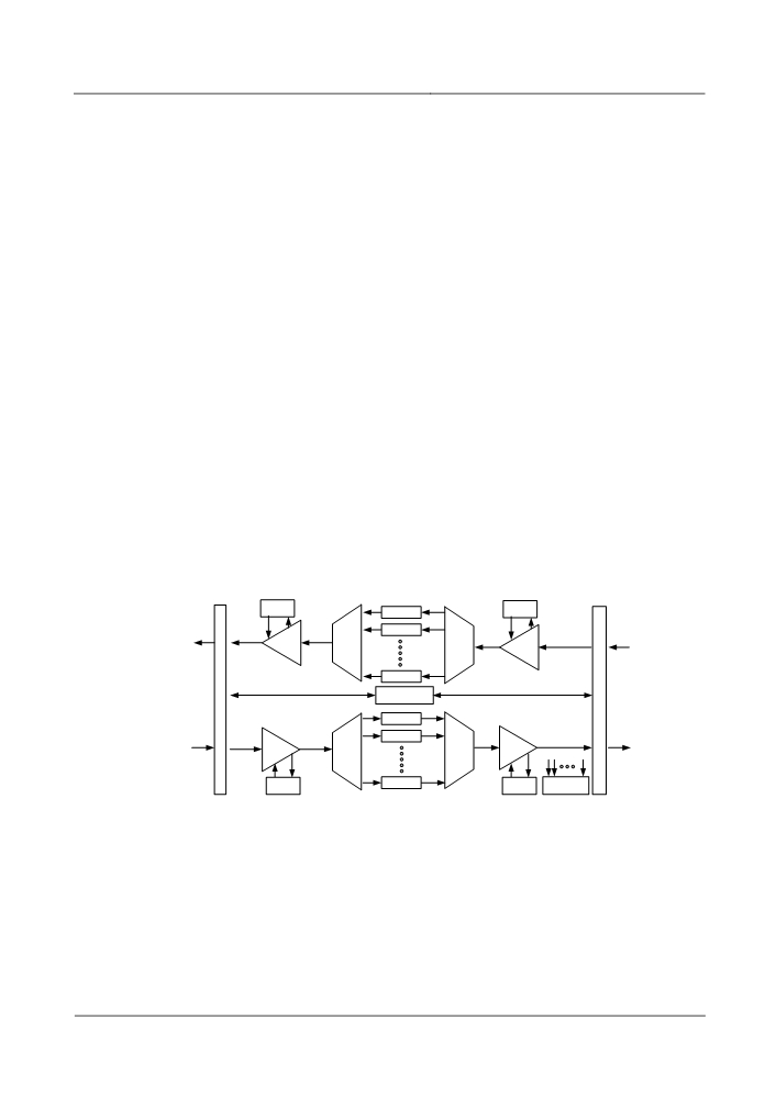
An REG station contains:
Optical transponder unit (OTU)
Optical multiplexer (OM)
Optical demultiplexer (OD)
Optical amplifier (OA)
Optical supervisory channel unit or supervisory channel and timing
transporting unit (OSC/OTC)
Fibre interface unit (FIU)
Multi-channel spectrum analyser unit (MCA)
System control & communication unit (SCC)
Power backup unit (PBU)
Figure 3-22 shows the block diagram of the REG signal flow.
DCM
λ01
DCM
OTU01
λ02
OTU02
OA
OM
OD
OA
λn
OTU n
F
F
OSC/OTC
I
I
U
U
λ01
OTU01
λ02
OTU02
OA
OM
OA
OD
λn
DCM
OTU n
DCM
MCA
Figure 3-22 REG signal flow
The signal flow of the REG is similar to that of back-to-back OTMs, except that no
signal is added/dropped. Signals are regenerated through the regenerating OTU.
3.4.2 Structure
For the REG of the six system types, each functional unit and the board(s)
contained are shown in Table 3-1.
3-29
3 System Configuration
The structure of the OM, OD, and OA of the six system types is the same as that of
the OTM equipment, as shown in Figure 3-2 and Figure 3-3.
3.4.3 Typical Configuration
The configuration of the REG is basically equivalent to that of two back-to-back
OTMs, following the same configuration rule.
Difference:
The REG needs to be configured with a bidirectional OSC/OTC or a pair of
OSCs/OTCs for backup.
The REG needs to be configured with two FIU boards.
The REG needs the regenerating OTU.
The configuration of the REG of 20-channel application in type III system is the
same as that shown in Figure 3-21.
3.4.4 Configuration Principle
The configuration principle of the REG is the same as that of the OTM.
3.5 OEQ
3.5.1 Signal Flow
In the extra long haul (ELH) application, as the transmission distance without the
regenerator is much longer than that in the long haul application, the following
problems may occur.
Accumulation of non flatness of optical amplifier gain spectrum and fibre
attenuation spectrum causes disequilibrium of both the optical power and
signal-to-noise ratio at the receive end.
The dispersion slope of DCM does not match with optical fibres completely, so all
wavelengths cannot be compensated completely, and the dispersion at the receive
end fails to meet the requirement of the system.
To better realise optical power equalization and dispersion compensation, the OEQ
is used in the ELH application. Currently, the type II and II systems can realise ELH
transmission.
The OEQ equipment consists of the optical power equaliser and the dispersion
equaliser.
(1) Optical power equaliser
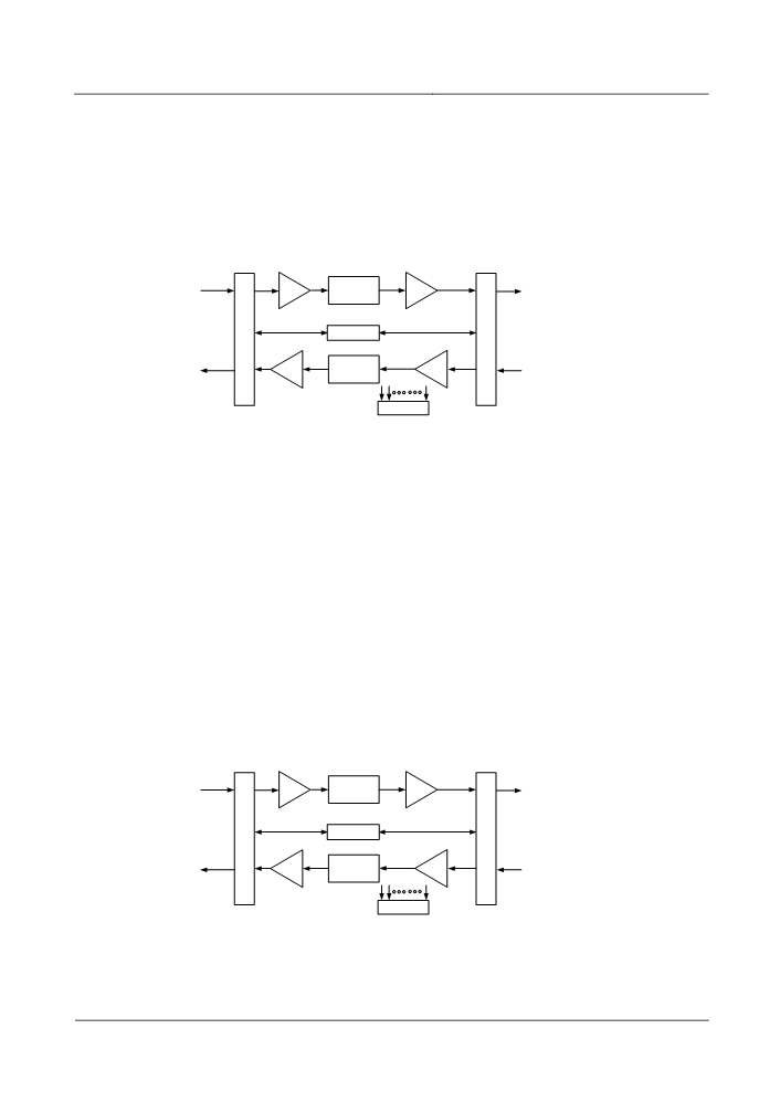
It consists of:
Optical power equaliser (OPE)
Optical amplifier (OA)
3-30
3 System Configuration
Optical supervisory channel unit or supervisory channel and timing
transporting unit (OSC/OTC)
Fibre interface unit (FIU)
Multi-channel spectrum analyser unit (MCA)
System control & communication unit (SCC)
Figure 3-23 shows the signal flow of the optical power equaliser.
OA
OPE
OA
F
F
OSC/OTC
I
I
U
U
OA
OPE
OA
MCA
Figure 3-23 Signal flow of optical power equaliser.
(2) Dispersion equaliser
It consists of:
Dispersion equaliser (DE)
Optical amplifier (OA)
Optical supervisory channel unit or supervisory channel and timing
transporting unit (OSC/OTC)
Fibre interface unit (FIU)
Dispersion compensation module (DCM)
Multi-channel spectrum analyser unit (MCA)
System control & communication unit (SCC)
Figure 3-24 shows the signal flow of dispersion equaliser.
OA
DE
OA
F
F
OSC/OTC
I
I
U
U
OA
DE
OA
MCA
Figure 3-24 The signal flow of dispersion equaliser
3-31
3 System Configuration
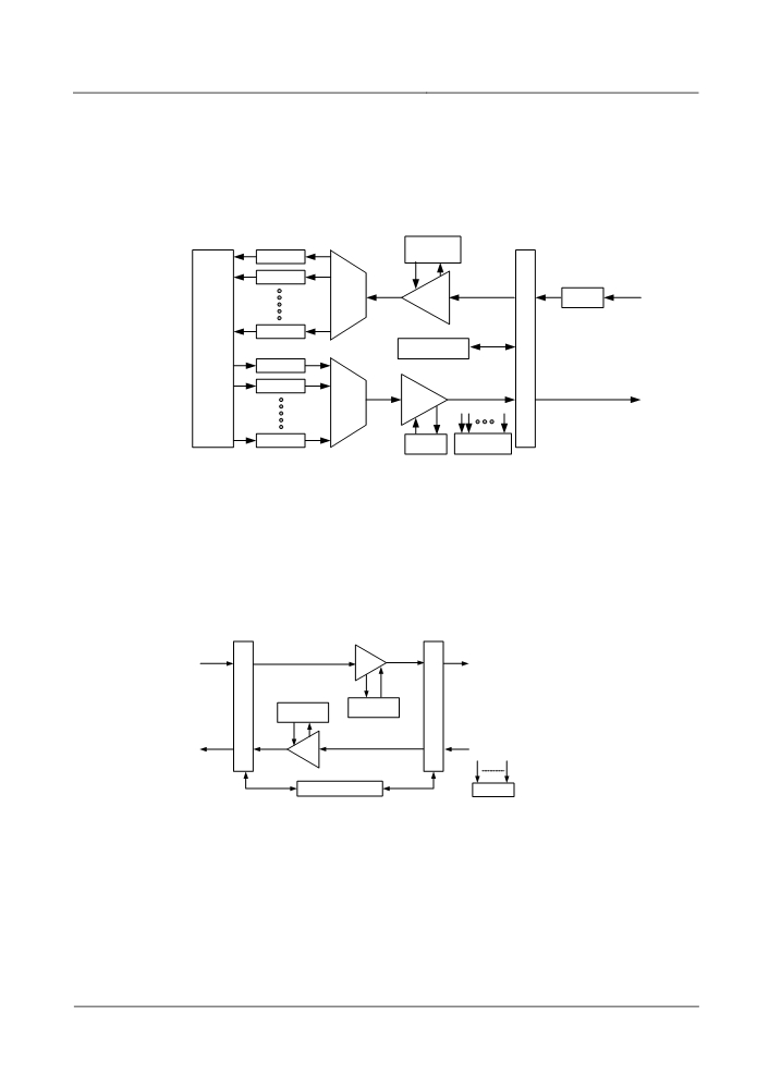
The dispersion equaliser and the optical power equaliser can be placed in the same
station.
The dispersion equaliser is often placed at the receive end of the OTM for
dispersion equalization, as shown in Figure 3-25 . It is recommended to place it at
the receive end of the last station in the optical multiplexing section.
λ01
DE
OTU01
λ02
OTU02
OD
OA
RPU
λn
OTU n
F
Client
OSC/OTC
I
side
λ01
U
OTU01
λ02
OTU02
OA
OM
λn
OTU n
DCM
MCA
Figure 3-25 Signal flow of dispersion equaliser in OTM
3.5.2 Structure
Optical power equaliser
Two solutions are available: use of the dynamic gain equaliser unit (DGE) and use
of the VMUX unit, as shown in Figure 3-26 and Figure 3-27.
C-EVEN
OAU
F
F
I
DGE+DCM
I
DGE+DCM
U
U
C-EVEN
OAU
SC2/TC2
MCA-C
DGE: Dynamic gain equaliser unit
OAU: Optical amplifier unit
DCM: Dispersion compensation module
FIU: Fibre interface unit
SC2: Bidirectional optical supervising channel unit
Figure 3-26 Optical power equalization through the DGE
As shown in Figure 3-26, the optical power equaliser unit consists of the DGE and
DCM. The DGE realises optical power equilibrium of each channel by adjusting
insertion loss spectrum of the DGE board. The DCM is used to realise dispersion
compensation of the system.
3-32
3 System Configuration
This solution has all the functions of the OLA. In addition, optical power
equilibrium is implemented to make the multiplexed signals meet the requirement
for optical power flatness, and to extend the transmission distance without
regeneration.
Note
For DGE solution, note whether the power margin of the OAU meets the insertion
loss requirement of the DCM and the DGE. If the margin cannot meet the
requirement, OAU+OBU should be adopted. DCM and DGE are placed between
two amplifiers.
C-EVEN
OAU
D40
V40
OBU
F
F
I
SC2
I
U
U
C-EVEN
OBU
V40
D40
OAU
V40: 40-channel multiplexing unit with VOA
D40: 40-channel demultiplexing unit
OBU: Optical booster unit
FIU: Fibre interface unit
SC2: Bidirectional optical supervisory channel unit
OAU: Optical amplifier unit
Figure 3-27 Optical power equalization through the VMUX (the V40 board)
In Figure 3-27, the VMUX is adopted. The V40 is used as the VMUX unit to adjust
optical power of each channel, so as to equalize optical power.
The user can select one of the solutions according to the actual requirement.
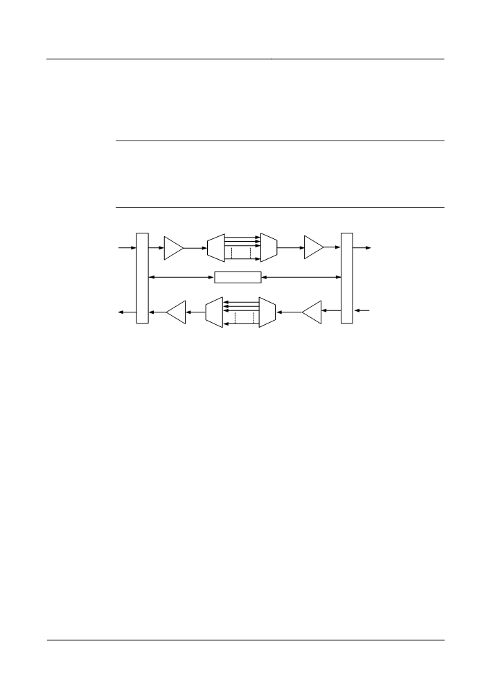
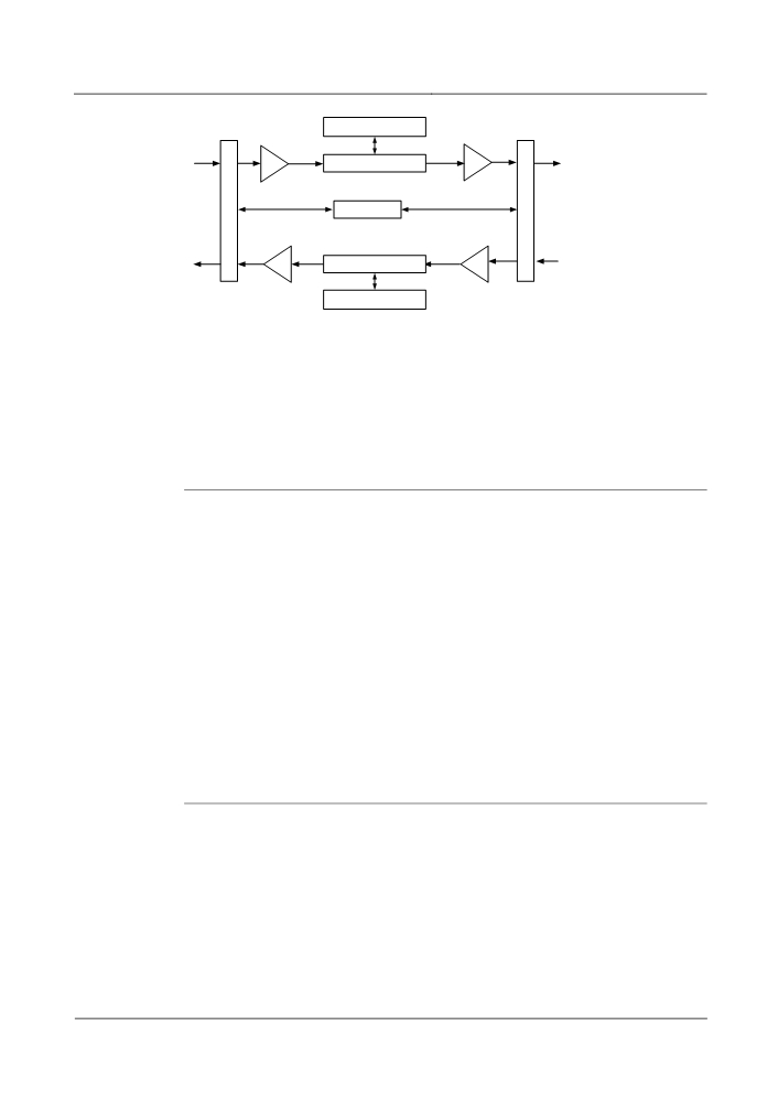
Dispersion equaliser
The dispersion equaliser realises equalised compensation of dispersion for
multiplexed signals, as shown in Figure 3-28.
3-33
3 System Configuration
DCM
OAU
DSE
OBU
F
F
I
SC2
I
U
U
OBU
DSE
OAU
DCM
DSE: Dispersion slope equaliser unit
OAU: Optical amplifier unit
OBU: Optical booster unit
SC2: Bidirectional optical supervising channel unit
FIU: Fibre interface u nit
DCM: Dispersion compensation module
Figure 3-28 Composition of dispersion equaliser
Through the dispersion slope equaliser (DSE), the system sends the multiplexed
signals to the DCM for equalised compensation for dispersion.
Note
In ultra-long haul transmission, the configuration of the optical equaliser should
follow the principles below.
1. In the case of "8 ≤ number of optical amplification sections ≤ 12", and without
configuration of the OEQ, the VMUX must be configured at the transmit end for
equalisation.
2. In the case of "number of optical amplification sections ≥ 12", the OEQ must be
configured. The subsequent optical amplification sections will be configured
differently according to OEQ solution.
(a) D40+V40 solution: An OEQ is added when 8 optical amplification sections are
added.
(b) DGE solution: An OEQ is added when 5 optical amplification sections are
added.
If the optical fibre length of multiplexing section is equal to or greater than 1000 km,
a dispersion equaliser is required.
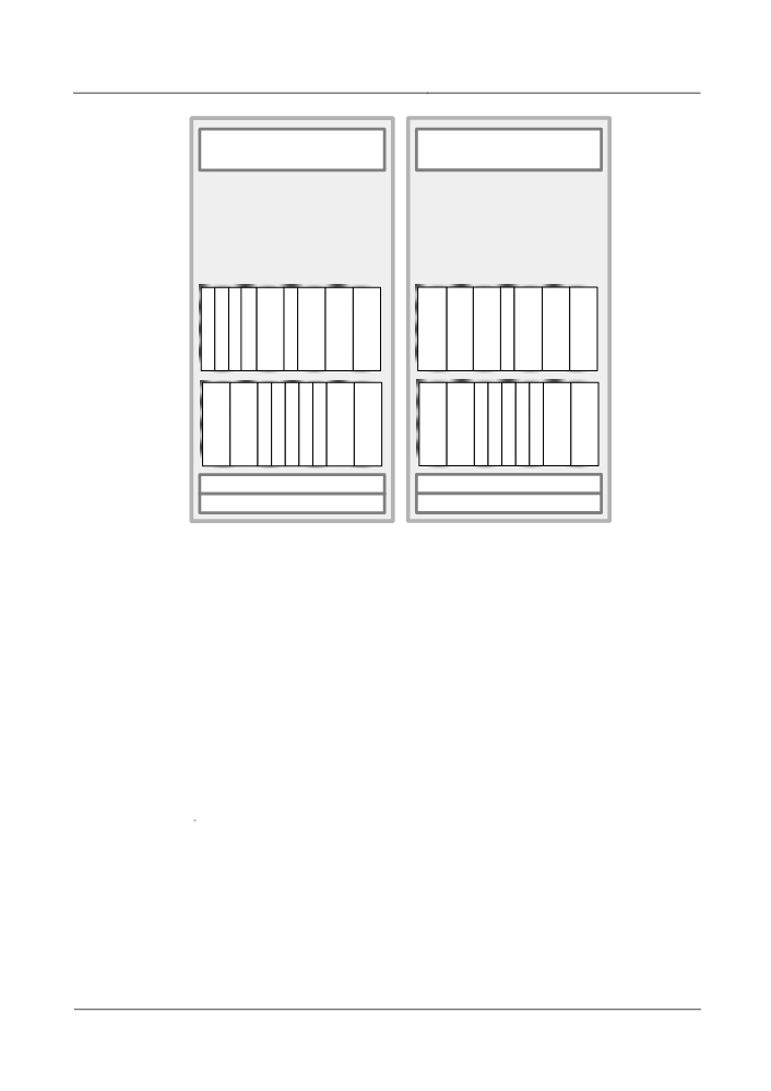
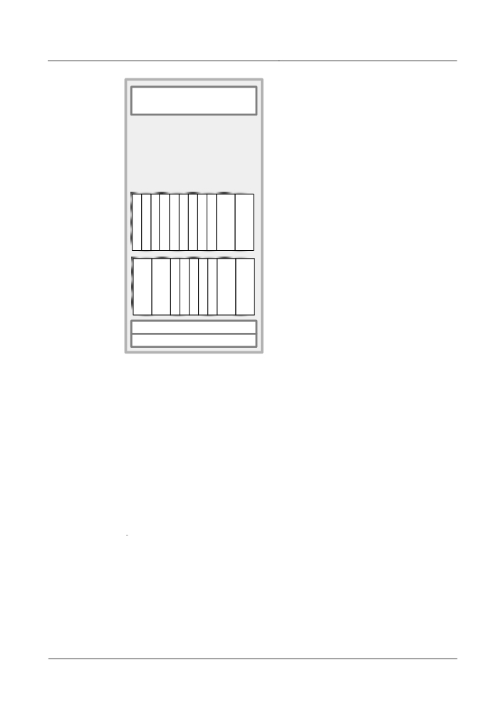
3.5.3 Typical Configuration
Figure 3-29 shows the configuration of the optical equaliser in the type III system.
Figure 3-30 shows the configuration of the dispersion equaliser in the type III
system.
3-34
3 System Configuration
Power
Power
M
S
V
D
M
S
D
V
C
C
4
4
C
C
4
4
A
E
0
0
A
E
0
0
(C)
(C)
O
D
F
T
S
F
D
O
O
O
F
T
S
F
O
O
A
G
I
C
C
I
G
A
A
B
I
C
C
I
B
A
U
E
U
2
C
U
E
U
U
U
U
2
C
U
U
U
(C)
(C)
(C)
(C)
(C)
(C)
DCM
DCM
HUB
HUB
Solution 1: DGE
Solution 2: V40+D40
Note: The "(C)" indicates the C band.
Figure 3-29 Configuration of OEQ
3-35
3 System Configuration
Power
F
S
F
M
I
C
I
C
U
E
U
A
(C)
O
O
D
T
S
D
O
O
A
B
S
C
C
S
B
A
U
U
E
2
C
E
U
U
(C)
(C)
(C)
(C)
DCM
HUB
Note: The "(C)" indicates the C band.
Figure 3-30 Configuration of dispersion equaliser
3.5.4 Configuration Principle
The configuration principle of the OEQ is the same as that of the OLA.
The OEQ (DGE and DSE) is inserted following "west on the left and right on the
east".
3-36
4 Networking and System Applications
4
Networking and System Applications
4.1 Networking and Applications
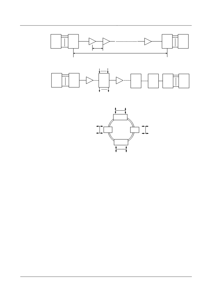
As shown in Figure 4-1, the OptiX BWS 1600G can be used in point-to-point
network, chain network and ring network, all of which can realize long haul, ultra
long haul, or ultra long haul and long hop application under different system
configurations and technologies.
4-1
4 Networking and System Applications
OLA
OLA
OLA
(#1)
(#2)
(#n-1)
Client
OTM
OTM
Client
1~160
mdB
1~160
n×m dB
Point-to-point network
ADD
Client
OTM
OLA
OADM
OLA
OEQ
REG
OTM
Client
1~160
1~160
DROP
Chain network
λ
1
λ 160
Back-to-back
OTM
λ
1
λ
1
OADM
OADM
λ
λ
80
80
Back-to-back
OTM
λ
1
λ 160
OTM:Optical terminal multiplexer
OLA:Optical line amplifier
OADM:Optical add/drop multiplexer
Ring network
OEQ:Optical equalizer
REG:Regenerator
Figure 4-1 OptiX BWS 1600G networking diagram
Point-to-point
The point-to-point network, composed of OTM and OLA, is the most prevalent
networking mode adopted by the OptiX BWS 1600G.
Chain
The chain network is frequently used in a national DWDM backbone network that
is of high capacity and long distance. A chain network may comprise OTM, OLA,
OADM, REG and OEQ, and can be regarded as the extension of a point-to-point
network.
Ring
The ring network is largely used in regional networks. It may comprise OADMs or
back-to-back OTMs depending on the practical situation. In practice, one OADM
in the DWDM ring network may be composed of back-to-back OTMs to remove
the accumulated noise caused by the amplifier.
4-2

4 Networking and System Applications
4.1.1 Type I system
The type I system, adopting non return to zero (NRZ) encoding, is applied in G.652
or G.655 optical fibers. Table 4-1 shows its networking capability.
Table 4-1 Networking capability of the type I system (160-channel, NRZ)
Classification
Specification
Typical distance
With FEC
1 × 28 dB
1 × 101 km (101 km)
2 × 24 dB
2 × 87 km (174 km)
5 × 20 dB
5 × 72 km (360 km)
The span attenuation is the actual attenuation of fibers, not including the loss of any optical
components.
Note
In section 4.1
, the span attenuation is the actual attenuation of the fiber, that is, the
difference between the output optical power of the local station and the input
optical power of the downstream station, not including the attenuation of the FIU
board.
In section 4.1
, the typical distances in the networking specification are calculated
on condition that the fiber attenuation coefficient is 0.275 dB/km.
The Raman amplifier can suppress OSNR from deteriorating to support more spans,
and to transmit signals longer. With Raman amplification, the type I system
supports a transmission distance of 640 km without a regenerator.
If the type I system uses out-band AFEC, it can support longer transmission without
REG.
4.1.2 Type II system
The type II system supports C+L 800G and C 800G.
C+L 800G
The C+L 800G system, adopting NRZ encoding, is applied in G.652 or G.655
optical fibers. Table 4-2 shows its networking capability.
4-3